146
0 ...
20mA
0 ...
20mA
AO
GND
GND
AI
GND
AI
GND
AI
GND
AI
A
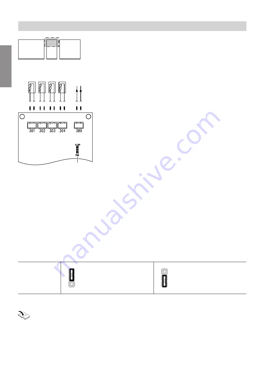
Fig. 90
d-A
HC 1: Flow temperature sensor, heating circuit 1
d-S
HC 2: Flow temperature sensor, heating circuit 2
or
TWE: Cylinder temperature sensor
d-D
TWE: Cylinder temperature sensor
or
SOL: Collector temperature sensor
or
HC 3: Flow temperature sensor, heating circuit 3
d-F
SOL: Cylinder temperature sensor, solar
d;Ö
SOL: Default speed for solar circuit pump
A
Jumper for parameter settings, output
d;Ö
Factory setting: Closed (PWM), solar circuit pump
Note
The slot assignment on this PCB may differ subject to
the system version.
Information on the jumpers
Jumper
A
for output
d;Ö
0-10 V
PWM
Jumper at top:
Voltage signal 0...10 V
0-10 V
PWM
Jumper at bottom:
PWM signal
System-specific slot assignment:
"System examples"
Connection and wiring diagram
PCB HKK 2.01
5679249
Appendix


