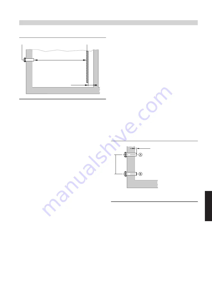
Deflector
≥200 mm
A
B
C
A
Fill connector
B
Deflector (1000 x 1200 mm)
C
Fill width approx. 4 - 5 m
Install deflector
B
at least 100 mm from the wall opposite the fill con-
nector. This deflector protects the pellets as well as the brickwork or
the render/plaster.
Pieces of plaster, render or wall that have been knocked off can hinder
the pellet supply and the combustion chamber ash removal.
Pellet supply hose and return air hose in conjunction with
Vitoligno 300-H with vacuum system
■
Room discharge with screw conveyor system:
–
Max. length
of the supply hose
15 m
.
–
Max. length
of the supply hose
plus
the return air hose
30 m
.
– To determine the required hose length, calculate the distance
between the pellet hopper connector and the pellet discharge point
from the pellet storage room or the pellet silo.
– Use the shortest path from the storage room to the boiler. Route
hoses so that they cannot be stepped on.
■
Room discharge with suction wands and manual changeover
unit:
–
Max. length
of the supply hose
and
return air hose from the boiler
to the furthest wand
15 m
.
– Max. height differential between the boiler and furthest wand
5 m
.
– Select the shortest path from the changeover unit to the suction
turbine and route hoses so that they cannot be stepped on.
However, hoses should be long enough to enable all hoses to be
connected to any position on the changeover unit. This is neces-
sary to allow the wand to purge the pellet supply hose with return
air if required.
■ Never kink the hoses; the smallest bending radius should be
300 mm.
■ Hoses should be routed as straight and level as possible. If hoses
are routed up and down repeatedly, pellets from lower areas cannot
be transported efficiently.
■ Hoses must be earthed to prevent static electricity building up during
pellet handling.
■ The pellet supply hose must be a single piece, whilst the return air
hose can be made up of several pieces. The connection piece should
be made of metal to ensure continuous earthing.
■ Never expose the hoses to temperatures above 60 °C, i.e. never
route them near heating pipes or flue pipes that are not thermally
insulated.
■ Never route outdoors (risk of becoming brittle due to UV radiation).
Fill connector and return air connector
Arrange the connectors so that no overpressure can develop in the
pellet storage room during the filling process. Keep the return air con-
nector unrestricted, even when the maximum filling level in the storage
room has been reached. The connectors should be located as high as
possible inside the pellet storage room to enable it to be filled to the
maximum. The fill connectors should be at least 20 cm below the ceil-
ing to prevent pellets hitting the ceiling (fit protective boards if the ceil-
ing is plastered). Choose a position for the connectors on the narrow
side of the storage room.
Pellets are blown approx. 4 to 5 m with straight fill connectors. Where
a 90° bend is located before the intake into the storage room, fit a
straight pipe of at least 1 m length on the other side to protrude into
the storage room. This enables the pellets to reach the required filling
velocity and therefore the required fill width.
Earth
Earth all connectors to prevent static electricity building up during the
filling process. Generally the connection of each pipe element to the
equipotential bonding of the building is recommended. At the very
least, connect each pipe element securely to the brickwork, either by
setting the pipe into the brickwork (without thermal insulation) or by
means of pipe clips set into the brickwork.
Connector length and location
The length of the fill connector depends on the distance to the return
air connector. Connector spacing of < 500 mm may occur if both con-
nectors are set into a cellar window.
~ 100
≥ 500
Connector spacing ≥500 mm
A
Fill connector
B
Return air connector
Fuel storage
(cont.)
VITOLIGNO 300-H
VIESMANN
45
5672 507 GB
6


