Note
No
physical layout is shown in
any
of the following connection diagrams.
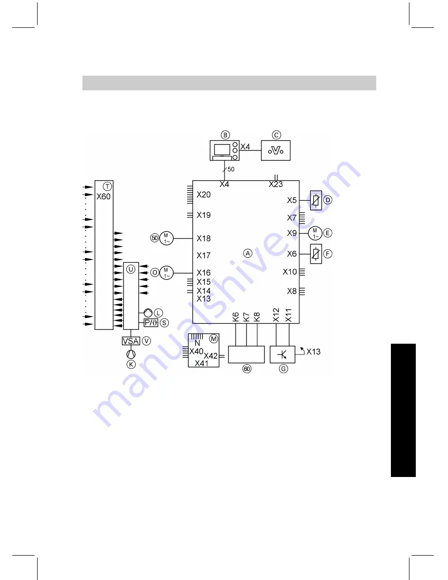
A
Main PCB
B
Programming unit
C
Optolink interface
D
Sensors
E
Stepper motor (internal)
F
Sensors and control inputs
G
Power supply unit
K
Compressor with control
L
Primary pump
M
Auxiliary PCB
O
Secondary pump
S
Safety chain
T
Main connecting area in control
panel 400/230 V
U
Control module (possibly with
phase monitor, accessories)
V
Full wave soft starter
tP
Cylinder primary pump
zP
Instantaneous heating water
heater (accessory)
X60. Main connection area for exter-
nal connections on the control
panel
Overview of the PCBs and connection options
175
Connection and wiring diagrams
55
92
968
GB
Service
Summary of Contents for VITOCAL 200-G
Page 8: ...Certificates Declaration of conformity 201 Keyword index 202 Index cont 8 Index 5592 968 GB ...
Page 122: ...Main menu Information Menu structure overview information 122 Control settings 5592 968 GB ...
Page 187: ...Parts lists cont 187 Parts lists 5592 968 GB Service ...
Page 188: ...Parts lists cont 188 Parts lists 5592 968 GB ...
Page 189: ...Parts lists cont 189 Parts lists 5592 968 GB Service ...
Page 206: ...206 5592 968 GB ...
Page 207: ...207 5592 968 GB ...


