Note
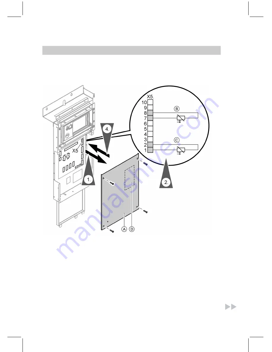
Subject to the DHW cylinder version, either one or two cylinder temperature
sensor(s) can be connected.
A
Remove main PCB cover
B
Lower cylinder temperature sen-
sor
C
Upper cylinder temperature sen-
sor
D
Attach type plate here (see
page 74)
1.
Remove main PCB cover by
undoing four screws and discon-
necting the earth strap.
2.
Connect sensor cable(s) to term-
inal strip X5 at top right on main
PCB as shown in illustration.
When only
one
cylinder tempera-
ture sensor is used, connect the
lead across
X5.1
and
X5.2
.
Electrical connection of the cylinder temperature sensor(s)
62
Installation sequence
55
92
968
GB
Summary of Contents for VITOCAL 200-G
Page 8: ...Certificates Declaration of conformity 201 Keyword index 202 Index cont 8 Index 5592 968 GB ...
Page 122: ...Main menu Information Menu structure overview information 122 Control settings 5592 968 GB ...
Page 187: ...Parts lists cont 187 Parts lists 5592 968 GB Service ...
Page 188: ...Parts lists cont 188 Parts lists 5592 968 GB ...
Page 189: ...Parts lists cont 189 Parts lists 5592 968 GB Service ...
Page 206: ...206 5592 968 GB ...
Page 207: ...207 5592 968 GB ...


