When using a separate heating circuit pump
Temperature limiter installation
instructions
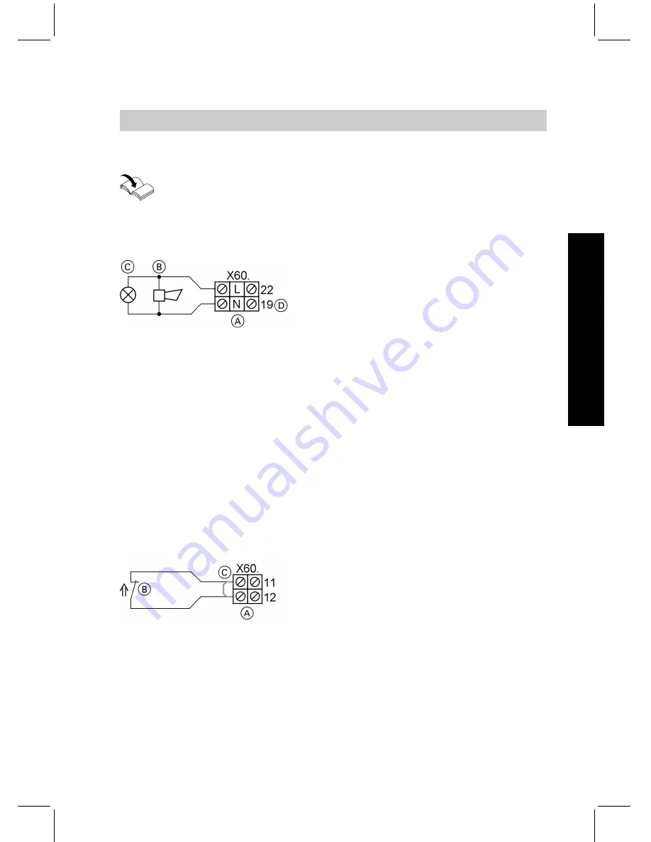
Central fault message
A
Terminals in the control panel
B
Acoustic alarm
C
Optical alarm
D
Alternatively, the neutral conduc-
tor can also be connected across
terminals X60.13 or X60.16
Breaking capacity: 230 V~, 0.7 A
Note
This contact is
not
at zero volt.
230 V~ will be present if there is a
fault.
Pressure switch, brine circuit
Note
If
no
brine circuit pressure switch is connected,
always
connect the jumper in
the pack downstream of the power supply. Always check the rotating field prior
to inserting the jumper.
A
Terminals in the control panel
B
Brine pressure switch
C
Jumper
The contact must be able to switch at
least 230 V and 0.7 A.
Note
Only use components in the safety
chain that do not automatically re-
start (reset). Where required, ensure
this through a mechanical interlock.
Making the electrical connections to external . . .
(cont.)
79
Installation sequence
55
92
968
GB
Installation
Summary of Contents for VITOCAL 200-G
Page 8: ...Certificates Declaration of conformity 201 Keyword index 202 Index cont 8 Index 5592 968 GB ...
Page 122: ...Main menu Information Menu structure overview information 122 Control settings 5592 968 GB ...
Page 187: ...Parts lists cont 187 Parts lists 5592 968 GB Service ...
Page 188: ...Parts lists cont 188 Parts lists 5592 968 GB ...
Page 189: ...Parts lists cont 189 Parts lists 5592 968 GB Service ...
Page 206: ...206 5592 968 GB ...
Page 207: ...207 5592 968 GB ...


