background image

115

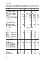
Type BW

1-stage

2-stage

190

1120

2150

2180

2250

Dimensions


Total length

mm

880

880

880

880

880

Total width

mm

1280

1280

1920

2520

2520

Total height without pro-
gramming unit

mm

1560

1560

1560

1560

1560

Connections


Primary flow and return

DN

3

3

3

3

3

Heating flow and return

DN

Weights

kg

720

820

1180

1240

1360

Sound emissions

 (tested

with reference to
EN 12102/EN ISO 1914-2)
Assessed total sound power
level at
B0 °C (±3 K)/W35 °C (±5 K)


At rated heating output

dB(A)

61.5

63

63

64

65

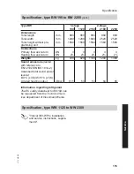
Information regarding refrigerant
The EC safety datasheet for R410A can
be requested from the Technical Serv-
ices department of Viessmann Werke.

Specification, type WW 1125 to WW 2300

"Vitocal 300-W Pro installation
and service instructions, supple-
ments".

Specification

Specification, type BW 190 to BW 2250

 (cont.)

5772 458 GB

Service


Summary of Contents for VITOCAL 300-G PRO Type BW 2150

Page 1: ... Pro Type BW 190 1120 2150 2180 2250 Vitocal 300 W Pro Type WW 1125 1155 2200 2250 2300 See also the Vitocal 300 W Pro installation and service instructions supplements For applicability see the last page VITOCAL 300 G PRO VITOCAL 300 W PRO 5772 458 GB 11 2011 Please keep safe ...

Page 2: ...working on this system National installation requirements Legal instructions regarding the pre vention of accidents Legal instructions regarding environ mental protection The Code of Practice of relevant trade associations All current safety regulations as defined by DIN EN DVGW VDE and all locally applicable standards a ÖNORM EN and ÖVE c SEV SUVA SVTI and SWKI Working on the system Isolate the s...

Page 3: ...eplace faulty components only with original Viessmann spare parts Auxiliary components spare and wearing parts Please note Spare and wearing parts that have not been tested together with the system can compromise its function Installing non author ised components and making non approved modifications or conversions can compromise safety and may invalidate our warranty For replacements use only ori...

Page 4: ...cade 31 Heat pump cascade 1 stage 2 stage 33 DHW heating 36 Installation sequence Installing the heat pump 38 Hydraulically connecting the primary secondary circuits 42 Routing cables to the heat pump terminal area 48 Overview of electrical connections 50 Power supply 67 Installing the programming unit 72 Closing the heat pump 73 Service instructions Commissioning inspection maintenance Steps comm...

Page 5: ... 2180 101 Casing type BW 2180 101 Electrical equipment type BW 2180 102 Parts list type BW 2250 Ordering parts 103 Refrigerant circuit type BW 2250 103 Casing type BW 2250 103 Electrical equipment type BW 2250 104 Parts list type WW 1125 to WW 2300 Parts list type WW 1125 to WW 2300 105 Commissioning service reports 106 Specification Specification type BW 190 to BW 2250 112 Specification type WW 1...

Page 6: ...yer refrigerant oil compressor filter oil separator 4 to 5 years subject to hours run and operating point Life cycle stages System operator Exter nal per son Manu facturer Refrig eration engi neer Logis tics Electri cian heating con tractor Service engi neer Disposal contrac tor Manufacture X X Delivery moving handling installation X X X X X Installation X X X Commissioning X X X X Operation X X M...

Page 7: ...act with live components can lead to serious injury from electric current Some compo nents on the PCBs will remain live even after the power supply has been switched off Isolate the system from its power supply e g at a sepa rate MCB fuse or mains isola tor check that there are no more live currents and safe guard against reconnection Note In addition to the control circuit there may be several po...

Page 8: ...e heat pump is in the intended condition Danger Falling of heavy or unwieldy heat pump components can result in life threatening crushing or breaks Always use suitable ropes slings and lifting gear when installing dismantling com pressors and heat exchangers for example Wear appropriate protective clothing e g safety boots in compliance with applicable regulations on accident pre vention and in li...

Page 9: ...gas that displaces air Unregulated escape of refrigerant R410A in enclosed spaces can result in dif ficulties in breathing and suffoca tion Never breathe in refrigerant vapours Ensure adequate ventilation in enclosed spaces Prevent open flames Observe and adhere to regula tions and guidelines about han dling refrigerant Danger Direct contact with refrigerant can harm skin Only work on the refriger...

Page 10: ...0 Type WW 1125 1155 Two stage heat pumps Type BW 2150 2180 2250 Type WW 2200 2250 2300 Criteria Integral heat pump control unit Vitotronic 200 type WO1B The refrigerant circuit has an elec tronic expansion valve EEV with an independent control circuit EEV con troller The heat pump control unit can switch and regulate one cooling circuit The cooling circuit may be a heating circuit prepared on site...

Page 11: ...se inside the ter minal area and must be fitted and con nected on site page 72 Accessories such as the flow switch and temperature sensors for exam ple are supplied separately The Vitocal 300 G Pro Vitocal 300 W Pro are filled with oil and refrigerant at the factory Unloading and transportation Note Before unloading have the recipient check the consignment for possible damage Note down any damage ...

Page 12: ...ting The centre of gravity of the Vitocal 300 G Pro Vitocal 300 W Pro lies through the heat exchanger on the l h side Always avoid impact and shocks to prevent damage to the internal pipework of the heat pump Avoid severely tipping the com pressor to safeguard the refrig erant circuit Max heat pump tilting angle 30 The KWT Kälte Wärmetechnik AG company which is a member of the Viessmann Group will...

Page 13: ...hackle B Cross beams to remove the load on the frame C Edge protection e g two or three layers of corrugated cardboard D Strap approved for the shipping weight Preparing for installation Delivery and installation cont 5772 458 GB Installation ...

Page 14: ... of corrugated cardboard Installation Installation room requirements Please note The installation room must be dry and free from the risk of frost Safeguard ambient temperatures of 0 to 35 C Please note Avoid the risk of explosion due to dust gases and vapours in the installation room Please note Observe the permissible floor load Total weight type BW 190 to BW 2250 BW 190 720 kg BW 1120 820 kg BW...

Page 15: ...al country specific regulations also apply Min room volume type BW 190 to BW 2250 BW 190 54 m3 BW 1120 68 m3 BW 2150 86 m3 BW 2180 103 m3 BW 2250 141 m3 Min room volume type WW 1125 to WW 2300 Vitocal 300 W Pro installation and service instructions sup plements Observe the required floor area and minimum clearances see the follow ing chapter Minimum clearances E 250 600 1500 A C B D E 250 500 1000...

Page 16: ...he heat pump removed on site 890 mm 1000 600 D 1000 4360 E D Note When installing cascades observe the relevant minimum clearances Sound attenuating plinth Position the heat pump on a base pre pared on site for the purpose of noise attenuation and uniform weight distribu tion Note In the case of corner installation enlarge the base by the minimum clearances see previous chapter Preparing for insta...

Page 17: ... per reg ulations E Pressure tested sound insulation layer approx 10 to 20 mm Pressure points of the adjustable heat pump feet Type BW 190 BW 1120 1380 980 1118 718 F E E Pressure tested sound insulation layer approx 10 to 20 mm F Front of the heat pump Preparing for installation Installation cont 5772 458 GB Installation ...

Page 18: ...ayer approx 10 to 20 mm F Front of the heat pump Type BW 2180 BW 2250 WW 1125 WW 1155 WW 2200 WW 2250 WW 2300 980 1265 1093 718 2620 F E E Pressure tested sound insulation layer approx 10 to 20 mm F Front of the heat pump Preparing for installation Installation cont 5772 458 GB ...

Page 19: ...0 370 328 533 1060 1256 490 1280 880 400 V 230 V 42 V 400 V 230 V 42 V A B C D A Primary circuit brine inlet Victaulic 3 B Secondary circuit flow Victaulic 2 C Primary circuit brine outlet Victaulic 3 D Secondary circuit return Victaulic 2 Preparing for installation Installation cont 5772 458 GB Installation ...

Page 20: ...70 1400 1920 880 490 400 V 230 V 42 V A B C D A Primary circuit brine inlet Victaulic 3 B Secondary circuit flow Victaulic 2 C Primary circuit brine outlet Victaulic 3 D Secondary circuit return Victaulic 2 Preparing for installation Installation cont 5772 458 GB ...

Page 21: ...y circuit brine inlet Victaulic 3 B Secondary circuit flow Victaulic 2 C Primary circuit brine outlet Victaulic 3 D Secondary circuit return Victaulic 2 Dimensions type WW 1125 to WW 2300 Vitocal 300 W Pro installation and service instructions supple ments Preparing for installation Installation cont 5772 458 GB Installation ...

Page 22: ...outing in empty pipes or ducts at an ambient tempera ture of max 25 C In the case of routing in the vicinity of heating pipes or encapsulated routing the cross sections and max cable lengths must be recalculated on site Load circuit 400 V on site control circuit 230 V wired at the factory Type Cable cross section Max cable length BW 190 WW 1125 5 x 25 mm2 40 m BW 1120 WW 1155 5 x 35 mm2 40 m BW 21...

Page 23: ... must be supplied with power without blocking by the power supply utility This means a sep arate power supply is required for the control circuit A separate connection for the control circuit calls for the internal wiring to be changed This may only be carried out by a heating contractor according to the electrical wiring diagram The control circuit power supply and the cable for the power OFF sig...

Page 24: ...3 8 3 9 P Required equipment Pos Designation 1 Heat pump 2 Heat pump control unit qT Primary pump fail safe wP Brine safety assembly wQ Pressure switch primary circuit wW Brine distributor for geothermal probes collectors wU Geothermal probes geothermal collectors Preparing for installation Primary circuit brine water 1 stage 5772 458 GB ...

Page 25: ...on and wiring diagram Primary circuit brine water 2 stage type BW 2150 BW 2180 BW 2250 Hydraulic installation scheme 22 27 20 21 1 15 2 211 1 P1 25 2 224 2 P1 2 KM BUS 230 V F2 211 1 F3 224 2 LP1 X3 8 3 9 2 LP1 X3 8 3 9 P Preparing for installation Primary circuit brine water 1 stage cont 5772 458 GB Installation ...

Page 26: ...l probes collectors wT Optional Second primary pump fail safe for stage 2 Note Contactor relay required Size first primary pump qT for partial load wU Geothermal probes geothermal collectors Electrical installation scheme For a summary of electrical connections see from page 50 and separate con nection and wiring diagram Preparing for installation Primary circuit brine water 2 stage cont 5772 458 ...

Page 27: ...tion scheme 22 27 20 21 9 P1 25 P1 P1 15 2 KM BUS 230 V F2 211 1 F3 2 211 1 2 211 1 P1 1 2 KM BUS 230 V F2 211 1 F3 LP1 X3 8 3 9 LP1 X3 8 3 9 2 LP1 X3 8 3 9 P Preparing for installation Primary circuit brine water cascade 5772 458 GB Installation ...

Page 28: ... assembly wQ Pressure switch primary circuit wW Brine distributor geothermal probes collectors wT Primary pump heat pump II fail safe Note For 2 stage Vitocal 300 G Pro a primary pump can be used for stages 1 and 2 respectively wU Geothermal probes geothermal collectors Electrical installation scheme For a summary of electrical connections see from page 50 and separate con nection and wiring diagr...

Page 29: ... 22 20 2 211 1 27 23 21 P1 15 2 211 1 25 2 224 2 1 2 KM BUS 230 V F2 211 1 F3 224 2 P1 LP1 X3 8 3 9 LP1 X3 3 3 4 2 LP1 X3 8 3 9 2 LP1 X3 3 3 4 LP1 X3 8 3 9 2 LP1 X3 8 3 9 P Preparing for installation Primary circuit water water 1 stage 2 stage 5772 458 GB Installation ...

Page 30: ...2 Note Contactor relay required Size first primary pump qT for partial load wR Dirt trap wZ Well pump suction pump for groundwater fail safe connect via on site contactor with fuse protection wU Delivery well wI Return well Electrical installation scheme For a summary of electrical connections see from page 50 and separate con nection and wiring diagram Type WW 1125 to WW 2300 Hydraulic installati...

Page 31: ...W 190 to BW 2250 Hydraulic installation scheme 19 24 26 28 22 20 27 23 21 9 P1 P1 25 1 P1 P1 15 2 KM BUS 230 V F2 211 1 F3 2 KM BUS 230 V F2 211 1 F3 2 211 1 2242 2 211 1 2 211 1 2 LP1 X3 8 3 9 2 LP1 X3 3 3 4 LP1 X3 8 3 9 LP1 X3 3 3 4 LP1 X3 8 3 9 LP1 X3 3 3 4 2 LP1 X3 8 3 9 P Preparing for installation Primary circuit water water 1 stage 2 stage cont 5772 458 GB Installation ...

Page 32: ...emove jumper when connecting wR Dirt trap wT Primary pump heat pump II fail safe Note For 2 stage Vitocal 300 G Pro a primary pump can be used for stages 1 and 2 respectively wZ Well pump suction pump for groundwater fail safe connect via on site contactor with fuse protection wU Delivery well wI Return well Electrical installation scheme For a summary of electrical connections see from page 50 an...

Page 33: ...on of the heat pumps within the cascade Up to max 3 lag heat pumps when connecting via KM BUS in conjunction with the external extension H1 see page 66 and separate service instructions for heat pump control unit Vitotronic 200 Up to 4 lag heat pumps when connect ing via LON see separate service instructions for heat pump control unit Vitotronic 200 The following communication modules accessories ...

Page 34: ...4 Hydraulic installation scheme qT wT 1 2 W P H C 5 7 qT wT 1 2 5 7 1 2 5 7 1 2 5 3 7 qT wT qT wT 6 6 6 6 IV 4 III 4 II 4 I 4 Preparing for installation Heat pump cascade 1 stage 2 stage cont 5772 458 GB ...

Page 35: ...lead heat pump I or LON communication module for lag heat pumps II to IV 5 First secondary pump fail safe 7 Only for 2 stage heat pumps type BW 2150 BW 2180 BW 2250 WW 2200 WW 2250 WW 2300 Second secondary pump fail safe Note Contactor relay required Size first secondary pump 5 for partial load qT First primary pump fail safe wT Optional Second primary pump fail safe for stage 2 Note Contactor rel...

Page 36: ...r WW DHW Required equipment Pos Designation eP DHW cylinder eW Cylinder temperature sensor eE Cylinder primary pump DHW side fail safe eR Plate heat exchanger eT Flow limiter eZ Motorised 2 way valve normally closed Note Permissible cylinder temperatures Top section Max 50 C Average cylinder temperature 45 C Size the plate heat exchanger eR in accordance with the technical guide Preparing for inst...

Page 37: ...9 Parameter Setting System definition System scheme 7000 0 2 4 6 8 10 DHW heating Time program DHW Set time program see op erating instructions Time prog DHW circ Set time program see op erating instructions DHW Enable booster heaters for DHW heating 6014 1 Enable electric heaters for DHW heating 6015 1 External heat source Enable external heat source for DHW heating 7B0D 0 Preparing for installat...

Page 38: ...el the heat pump hori zontally as described on page 14 Removing the top panel Note For type BW 2180 BW 2250 and WW 1125 to WW 2300 only the l h sec tion of the top panel must be removed Installation sequence Installing the heat pump 5772 458 GB ...

Page 39: ...39 1 2 3 Installation sequence Installing the heat pump cont 5772 458 GB Installation ...

Page 40: ...cessive noise Remove and dispose of all trans port brackets correctly Number of transport brackets Type Transport bracket Frame screw Mounting clip BW 190 2 1 BW 1120 2 1 BW 2150 3 1 BW 2180 4 1 BW 2250 4 1 WW 1125 WW 1155 WW 2200 WW 2250 WW 2300 4 1 Installation sequence Installing the heat pump cont 5772 458 GB ...

Page 41: ...41 1 2 3 4 A B A Frame screw B Mounting clip Installation sequence Installing the heat pump cont 5772 458 GB Installation ...

Page 42: ... D A Primary circuit brine inlet Victaulic 3 B Secondary circuit flow Victaulic 2 C Primary circuit brine outlet Victaulic 3 D Secondary circuit return Victaulic 2 Installation sequence Hydraulically connecting the primary secondary circuits 5772 458 GB ...

Page 43: ...r 3 primary circuit couplings B Flexible connecting cable with sound insulation elements C Optional Flange with 2 secon dary circuit or 3 primary circuit thread D Fastening of the hydraulic lines Installation sequence Hydraulically connecting the primary secondary cont 5772 458 GB Installation ...

Page 44: ...taulic 2 secondary circuit or 3 primary circuit couplings B Adapter nipple with flange DN80 PN10 without sound insulation ele ments C Silencing compensators on site D Fastening of the hydraulic lines Installation sequence Hydraulically connecting the primary secondary cont 5772 458 GB ...

Page 45: ... Push connection line C connection set or adaptor nipple with flange D flanged Victaulic adaptor set as far as it will go into Victaulic coupling B 5 Close Victaulic coupling B flush and tighten until there is no more gap 6 Carry out a pressure test Connection overview Type WW 1125 to WW 2300 Vitocal 300 W Pro installation and service instructions supple ments Installation sequence Hydraulically c...

Page 46: ...all pipes routed through walls 3 Connect primary pipes to heat pump Please note To prevent damage to the appliance connect the pri mary lines to the heat pump free of load and torque stresses The primary lines must not exert any pressure onto the heat pump casing Please note Ensure the hydraulic connec tions on the primary side are tight in order to prevent the formation of condensation inside the...

Page 47: ...sing Please note Ensure the hydraulic connec tions on the secondary side are tight in order to prevent the formation of condensation inside the heat pump With line entries ensure the diaphragm grommets on the l h side panel are seated correctly Make line entries air tight 3 Fill and vent secondary circuit 4 Thermally insulate pipes inside the building Note In underfloor heating circuits integrate ...

Page 48: ...tely Strip the insulation from the cables as close to the terminals as possible and bundle tightly to the corresponding terminals Secure cables with cable ties strain relief fittings This ensures that should there be a fault for example when detaching a wire the wires can not drift into the adjacent voltage area When routing the on site power cables observe the location of the cable entries into t...

Page 49: ...bles and 230 V cables as far apart as possible 3 Route power cable for compressor through 400 V opening to the heat pump terminal area Always secure power cables with strain relief fittings Note Additional strain relief fittings are required on site as the wall clearance 80 mm For power supply see from page 67 Installation sequence Routing cables to the heat pump terminal area cont 5772 458 GB Ins...

Page 50: ...ed to the same terminal press both wires together into a single wire ferrule Terminal area top A C D E F H L K M G B F3 A Power supply power circuit com pressor 3 x 400 V 50 Hz B Mains isolator C Contactors for primary and secon dary pumps D Terminal strip for system compo nents consumers 3 x 400 V 230 V for connection see separate connection and wir ing diagram sheet 13 Switched phase can be used...

Page 51: ... BW 2150 BW 2180 BW 2250 WW 2200 WW 2250 WW 2300 Contactor compressor 2 P Only type BW 2150 BW 2180 BW 2250 WW 2200 WW 2250 WW 2300 Soft starter compressor 2 R Fuse MCB power circuit compres sor 1 S Contactor compressor 1 T Soft starter compressor 1 U Fuse MCB power circuit system components consumer at terminal strip D see separate connection and wiring diagram sheet 13 13F2 V Fuse MCB control ci...

Page 52: ...ues The output given is the recommended connected load The total output of all components con nected directly to the heat pump con trol unit e g pumps valves message facilities contactors must not exceed 1000 W If the total output is 1000 W the indi vidual output of a component e g pump valve messaging facility con tactor may be selected larger than specified However the breaking capacity of the c...

Page 53: ...53 F3 sXG sXF sXD sXS sYA sYS Set the required parameters during com missioning see from page 79 Installation sequence Overview of electrical connections cont 5772 458 GB Installation ...

Page 54: ...ection and wiring diagram sheet 110 211 5 NC Cooling control NC function natural cooling or NC signal for AC function active cooling Connection values Output 10 W Voltage 230 V Max switching current 4 2 A Circuit on site NC function see separate connection and wiring diagram sheet 191 sheet 192 AC function see separate connection and wiring diagram sheet 201 sheet 203 Installation sequence Overvie...

Page 55: ...erature limiter for un derfloor heating circuit if installed in series see following chapter Connection values Output 100 W Voltage 230 V Max switching current 4 2 A On site connection see separate con nection and wiring diagram sheet 120 Use contactor if required see separate connection and wiring diagram sheet 121 sheet 122 212 3 DHW circulation pump Connection values Output 50 W Voltage 230 V M...

Page 56: ... connection see separate con nection and wiring diagram sheet 170 sheet 171 sheet 172 222 2 Mixer motor control for ex ternal heat source Signal mixer OPEN Connection values Output 10 W Voltage 230 V Max switching current 0 2 0 1 A On site connection see separate con nection and wiring diagram sheet 170 sheet 171 sheet 172 Installation sequence Overview of electrical connections cont 5772 458 GB ...

Page 57: ...he boiler water temperature sensor in the external heat source plug F20 must capture the average temperature of the external heat source Connection values contact loads Voltage 230 V Max switching current 4 2 A Connect the high limit safety cut out on site In series with the secondary pump ter minal 211 2 on main PCB see sepa rate connection and wiring diagram sheet 20 In series for switching exte...

Page 58: ...onnection values Output 130 W Voltage 230 V Max switching current 4 2 A On site connection see separate con nection and wiring diagram sheet 150 Use contactor if required see separate connection and wiring diagram sheet 151 sheet 152 224 7 Circulation pump for DHW reheating Connection values Output 100 W Voltage 230 V Max switching current 4 2 A On site connection see separate con nection and wiri...

Page 59: ...otor control heating circuit M2 HC2 Signal mixer CLOSE Connection values Output 10 W Voltage 230 V Max switching current 0 2 0 1 A On site connection see separate con nection and wiring diagram sheet 130 Use contactor if required see separate connection and wiring diagram sheet 131 sheet 132 225 3 M2 Mixer motor control heating circuit M2 HC2 Signal mixer OPEN Connection values Output 10 W Voltage...

Page 60: ...tion terminal St 223 2 223 1 Set the required parameters during commissioning see from page 79 Connections see separate connec tion and wiring diagram sheet 13 sheet 21 Signal and safety connections Terminals Function Explanation PE X1 Earth conductor Terminals for earth conductor of all asso ciated system components LP1 X2 N Neutral conductor Terminals for the neutral conductor of the heat pump c...

Page 61: ...ee installation in structions External extension H1 If a swimming pool water heating facility is connected to external extension H1 no other external function can be con nected to external extension H1 LP1 X3 3 LP1 X3 4 Flow switch well circuit Floating contact required Closed Heat pump operational Open Heat pump shut down Breaking capacity 230 V 0 15 A There should be no jumper if a flow switch i...

Page 62: ...d in a 5 core cable For further information regarding power OFF see chapter Power supply LP1 X3 8 LP1 X3 9 P Primary circuit pressure switch and or frost stat or Jumper Floating contact required Closed Safety chain has continuity Open Safety chain interrupted heat pump shut down Breaking capacity 230 V 0 15 A On site connection Connected in series if both safety com ponents are installed Insert ju...

Page 63: ...1 see installation instruc tions External extension H1 If a swimming pool water heating facility is connected to external extension H1 no other external function can be con nected to external extension H1 K2 220 2 K2 220 3 Only for 2 stage heat pumps Blocking compressor 2 in connection with DHW heating Connection see separate connection and wiring diagram sheet 20 STB 1 STB 2 High limit safety cut...

Page 64: ... 2 A On site connection see separate connec tion and wiring diagram sheet 21 Note No parameters need to be set The contact issues a short pulse when the power supply is switched on Ob serve the pulse when processing the message via communication tools Controller and sensor PCB F0 F2 aVG F6 F7 F3 F4 F12 F8 F16 F13 F14 F21 F18 F20 X31 X5 X24 X6 Installation sequence Overview of electrical connection...

Page 65: ...er temperature sensor top connect on site Pt 500 PTC F7 Cylinder temperature sensor bottom connect on site Pt 500 PTC F12 Flow temperature sensor heating circuit with mixer M2 HC2 connect on site Ni 500 PTC F13 Flow temperature sensor system with sensor well downstream of heating water buffer cylinder connect on site Pt 500 PTC F14 Flow temperature sensor cooling circuit direct heating circuit A1 ...

Page 66: ...wimming pool heating Note Swimming pool heating is activated via external extension H1 with KM BUS Connections to external extension H1 only in accordance with the separate connection and wiring diagram sheet 180 sheet 181 sheet 182 Connect only the circulation pump for swimming pool heating to plug gÖ of external extension H1 A filter circuit pump must be connected separately If the components fo...

Page 67: ... Vitocal 300 W Pro is not possible The instantaneous heating water heater available as an accessory for the Vitocal 300 G 350 G 60 kW cannot be used Power supply Isolators for non earthed conductors The mains isolator simultaneously iso lates all non earthed conductors from the mains with a minimum contact sep aration of 3 mm We also recommend installing an AC DC sensitive RCD RCD class B for DC f...

Page 68: ...box to the heat pump control unit The allocation of the power OFF for compressor and or instantaneous heating water heater is made via the type of connection and by setting parameters in the heat pump control unit In Germany the power supply can be cut off for up to 3 x 2 hours per day 24 h The control unit feed heat pump con trol unit PCB must be supplied with power without blocking by the power ...

Page 69: ...s Note The specified cross sections and max cable lengths apply to routing in empty pipes or ducts at an ambient tempera ture of max 25 C In the case of routing in the vicinity of heating pipes or encapsulated routing the cross sections and max cable lengths must be recalculated on site Load circuit 400 V on site control circuit 230 V wired at the factory Type Cable cross section Max cable length ...

Page 70: ...l circuit must be supplied with power without blocking by the power supply utility This means a sep arate power supply is required for the control circuit A separate connection for the control circuit calls for the internal wiring to be changed This may only be carried out by a heating contractor according to the electrical wiring diagram The control circuit power supply and the cable for the powe...

Page 71: ...compressor Reduction in starting current of the compressor during its starting proce dure Delivered condition Rotating field phase asymmetry 20 Max compressor operating current Imax Subject to compressor output Overload protection This will separate the appliance from the mains automatically if the tolerance range of the electronic soft starter is exceeded Remove the cause if the relay has respond...

Page 72: ...ith the separate connection and wiring diagram sheet 11 and sheet 12 Installing the programming unit Note In its delivered condition the program ming unit is inside the terminal area of the heat pump Only fit the programming unit after all electrical connections have been made In order to install the programming unit position the top panel on top of the heat pump and push back far enough to make t...

Page 73: ...ound proof and diffusion proof Check tightness of internal hydraulic connections Please note To prevent the formation of con densate and the excessive devel opment of noise tightly seal the doors at the front Installation sequence Installing the programming unit cont 5772 458 GB Installation ...

Page 74: ...bles inside the terminal area securely fixed strain relief cable ties Has the programming unit been fit ted and connected Have all earth conductors been connected Have all cable entries grommets been correctly applied and sealed against moisture ingress Have all hydraulic connections been sealed airtight and been insu lated against heat loss and vapour diffusion Have transport brackets been remove...

Page 75: ...it for leaks 77 4 Filling and venting on the primary side 77 5 Filling and venting on the secondary side 77 6 Filling and venting the solar circuit 78 7 Checking expansion vessels and the primary circuit heating circuit pressure 79 8 Commissioning the system 79 9 Closing the heat pump 10 Instructing the system user 88 Commissioning inspection maintenance Steps commissioning inspection and maintena...

Page 76: ...ote Wait at least 30 min between the installation and commissioning of the appliance to prevent equip ment damage Work on the refrigerant circuit must only be carried out by a qualified refrigeration engi neer 1 Remove front panel see page 73 2 When the work is complete close the heat pump see page 73 Regarding commissioning this appliance see also the operating instructions Writing reports Enter ...

Page 77: ...ether so that there are no gaps 2 Check the pre charge pressure of the expansion vessel 3 Fill the primary circuit with Viessmann heat transfer medium and vent Note The system must be protected against frost down to 15 C Please note To prevent equipment dam age check the flow and return connections of the heat pump primary circuit for tightness In the case of leaks switch off the heat pump immedia...

Page 78: ...isplaced seals gas kets 5 Check the system pressure and top up with water if required Minimum system pressure 0 8 bar Permiss operating pressure 2 5 bar Filling and venting the solar circuit Danger Overheated collector areas and overheated heat transfer medium can cause burns scalding and equipment damage When working on the collector and the solar circuit with heat transfer medium protect the col...

Page 79: ...e Type and extent of parameters depend on the heat pump type on the selected system scheme and the accessories employed Commissioning with the commissioning wizard The commissioning wizard guides you automatically through all the menus where settings have to be made For this Coding level 1 is automatically active Please note Incorrect operation at Coding level 1 may result in damage to the applian...

Page 80: ...t pump control unit progress bar visible hold down When the unit is first commissioned the display is in German Sprache Dansk Cesky Bulgarski Deutsch Wählen mit ê ê ç DE BG CZ DK ê ê Manually switching some appliance components during commissioning enables the heat pump control unit to display messages These are not appliance faults Commissioning inspection maintenance Further details regarding th...

Page 81: ... Start commissioning Parameter group select Language set Date time set Temperature sensors Signal inputs Actuator test Subscriber check LON Commissioning terminated Control mode OK OK OK OK OK OK OK OK OK OK OK OK NO YES OK Function check Programming level 1 Commissioning inspection maintenance Further details regarding the individual steps cont 5772 458 GB Service ...
Page 82: ...also assigned to each parameter Service menu 1 Press OK å simultaneously for approx 4 s 2 Select Coding level 1 3 Select parameter group System definition 4 Select parameter System scheme 7000 5 Set system scheme 6 Alternatively if the service menu was already enabled Extended menu 1 å 2 Service 3 Select Coding level 1 4 Select parameter group System definition 5 Select parameter System scheme 6 C...

Page 83: ...mp and mixer M3 HC3 switched via mixer extension kit System definition Ó System scheme 7000 With heating circuit M3 for heating circuit with mixer M3 HC3 Note Set rotary switch S1 in the extension kit to 2 see ex tension kit installation in structions Circulation pump for cyl inder heating System definition Ó System scheme 7000 With DHW heating Internal hydraulics Ó Enable 3 way diverter valve hea...

Page 84: ...2003 or Heating circuit 2 Ó Remote control 3003 or Heating circuit 3 Ó Remote control 4003 1 Note Set code on the Vitotrol 200A to assign heating cir cuits H1 for heating circuit A1 HC1 H2 for heating circuit M2 HC2 H3 for heating circuit M3 HC3 see Vitotrol 200 A installa tion instructions Vitocom 100 System definition Ó Vitocom 100 7017 1 External extension H1 System definition Ó External extens...

Page 85: ...m components for external changeover 7011 0 to 10 System definition Ó Operating status for ex ternal changeover 7012 0 to 3 System definition Ó Duration of external changeover 7013 0 to 12 External blocking of compres sor and pumps System definition Ó Effect of external block ing on pumps compressor 701A 0 to 31 External blocking of the com pressor mixer in control mode or CLOSED System definition...

Page 86: ...le instantaneous heating water heater 7900 1 Poss Electr booster heater Ó Enable instant heating water heater for cen tral heating 7902 1 Electr booster heater Ó Output for instant heating water heater at power OFF 790A 1 for output stage 1 2 for output stage 2 3 for output stages 1 and 2 Poss DHW Ó Enable electric heaters for DHW heating 6015 1 External heat source External heat source parameters...

Page 87: ...em definition Ó Cascade control 700A 1 0 System definition Ó Number of lag heat pumps in cascade 5735 1 to 3 System definition Ó Output lag heat pump 700B 0 to 255 System definition Ó Use of heat pump in cascade 700C 0 to 15 System definition Ó Flow temperature for external demand 730C 0 to 700 0 to 70 C Cascade via LON Parameter Setting Lead appliance Lag heat pump System definition Ó System sche...

Page 88: ...nication module 7710 1 1 Communication Ó LON subscriber number 7777 1 to 99 unique 1 to 99 unique Communication Ó LON system number 7798 1 to 5 1 to 5 as per lead appliance Communication Ó LON fault manager 7779 1 to 99 unique 1 to 99 unique Note The additional parameters for the heat pump cascade are set during commis sioning by a certified heat pump contrac tor Instructing the system user The sy...

Page 89: ...etween the programming unit and the terminal area Carefully remove the top panel see page 38 2 Lean the top panel against a wall and secure against slippage with 2 screws service position 200 Overview of electrical components See from page 50 Troubleshooting Repairs 5772 458 GB Service ...

Page 90: ...90 Overview of internal components Type BW 190 to BW 2250 qP qQ qT qI qR qZ qO qU wQ wP wW 1 qW qE 2 3 4 5 8 9 6 7 Troubleshooting Repairs cont 5772 458 GB ...

Page 91: ...0 Suction gas temperature sensor EEV 2 Stage 2 8 Low pressure sensor EEV 1 Stage 1 9 Only type BW 2150 BW 2180 BW 2250 Low pressure sensor EEV 2 Stage 2 qP Liquid gas temperature sensor EEV 1 Stage 1 qQ Only type BW 2150 BW 2180 BW 2250 Liquid gas temperature sensor EEV 2 Stage 2 qW Electronic expansion valve EEV 1 Stage 1 qE Only type BW 2150 BW 2180 BW 2250 Electronic expansion valve EEV 2 Stage...

Page 92: ...d parallel filter dryer wW Condenser wE Evaporator wR Primary circuit return temperature sensor heat pump brine outlet wT Secondary circuit flow temperature sensor wZ Primary circuit flow temperature sensor heat pump brine inlet Overview of internal components Type WW 1125 to WW 2300 Vitocal 300 W Pro installation and service instructions supple ments Draining the heat pump on the primary secondar...

Page 93: ...4 Buffer temperature sensor F4 Cylinder temperature sensor F6 Flow return temperature sensor secondary circuit F8 F9 System flow temperature sensor F13 Boiler water temperature sensor external heat source F20 Pt 500 All sensors in the heat pump refrigerant cir cuit See page 90 Temperature sensors type Ni 500 400 40 20 0 Resistance in Temperature in C 440 480 520 560 600 20 40 60 640 Temperature se...

Page 94: ...p terminal area see page 50 Fuse MCB F3 on main PCB 6 3 A slow 250 V Max power loss 2 5 W Danger Contact with live components can lead to serious injury from electric current Before working on the equip ment always ensure that the power circuit is also at zero volt Removing the fuse does not switch the power circuit to zero volt Appliance too noisy Possible causes Transport bracket not removed Doo...

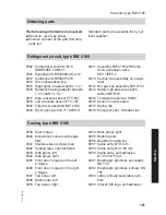
Page 95: ...51W 0035 Temperature sensor Pt500 0036 Sensor mount sealed 0037 Spring clip 0038 Emergency set Schrader tee Casing type BW 190 0039 Door hinges 0040 Mono block corners with edge filler 0041 Stainless steel screws set 0042 Sealing tape internal frame 0043 Side panel left 0044 Side panel right 0045 Front door hinged on the left 2 hinges 0046 Front door hinged on the right 2 hinges 0047 Top panel lef...

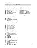
Page 96: ...3L 0099 Piggyback terminal L PE 0100 Piggyback terminal L N 0101 Piggyback terminal N PE 0102 Piggyback terminal 2L 0103 Piggyback terminal PE 0104 Separating cover for multi level terminal 0105 Cover for multi level terminal 0106 Cover for system component ter minal strip 0107 Strapping plug 0108 Strapping plug 0109 Mating plug for controller and sen sor PCB 0110 Vitotronic 200 WO1B 0111 Coding c...

Page 97: ...151W 0035 Temperature sensor Pt500 0036 Sensor mount sealed 0037 Spring clip 0038 Emergency set Schrader tee Casing type BW 1120 0039 Door hinges 0040 Mono block corners with edge filler 0041 Stainless steel screws set 0042 Sealing tape internal frame 0043 Side panel left 0044 Side panel right 0045 Front door hinged on the left 2 hinges 0046 Front door hinged on the right 2 hinges 0047 Top panel l...

Page 98: ...L 0099 Piggyback terminal L PE 0100 Piggyback terminal L N 0101 Piggyback terminal N PE 0102 Piggyback terminal 2L 0103 Piggyback terminal PE 0104 Separating cover for multi level terminal 0105 Cover for multi level terminal 0106 Cover for system component ter minal strip 0107 Strapping plug 0108 Strapping plug 0109 Mating plug for controller and sen sor PCB 0110 Vitotronic 200 WO1B 0111 Coding ca...

Page 99: ...line assembly BW 2150 0034 Safety high pressure switch ACB 2UB151W 0035 Temperature sensor Pt500 0036 Sensor mount sealed 0037 Spring clip 0038 Emergency set Schrader tee Casing type BW 2150 0039 Door hinges 0040 Mono block corners with edge filler 0041 Stainless steel screws set 0042 Sealing tape internal frame 0043 Side panel left 0044 Side panel right 0045 Front door hinged on the left 2 hinges...

Page 100: ...L 0099 Piggyback terminal L PE 0100 Piggyback terminal L N 0101 Piggyback terminal N PE 0102 Piggyback terminal 2L 0103 Piggyback terminal PE 0104 Separating cover for multi level terminal 0105 Cover for multi level terminal 0106 Cover for system component ter minal strip 0107 Strapping plug 0108 Strapping plug 0109 Mating plug for controller and sen sor PCB 0110 Vitotronic 200 WO1B 0111 Coding ca...

Page 101: ... line assembly BW 2150 0034 Safety high pressure switch ACB 2UB151W 0035 Temperature sensor Pt500 0036 Sensor mount sealed 0037 Spring clip 0038 Emergency set Schrader tee Casing type BW 2180 0039 Door hinges 0040 Mono block corners with edge filler 0041 Stainless steel screws set 0042 Sealing tape internal frame 0043 Side panel left 0044 Side panel right 0045 Front door hinged on the left 2 hinge...

Page 102: ...inal L PE 0100 Piggyback terminal L N 0101 Piggyback terminal N PE 0102 Piggyback terminal 2L 0103 Piggyback terminal PE 0104 Separating cover for multi level terminal 0105 Cover for multi level terminal 0106 Cover for system component ter minal strip 0107 Strapping plug 0108 Strapping plug 0109 Mating plug for controller and sen sor PCB 0110 Vitotronic 200 WO1B 0111 Coding card SA883 B20 RE WP 01...

Page 103: ...ssembly BW 2180 BW 2250 0034 Safety high pressure switch ACB 2UB151W 0035 Temperature sensor Pt500 0036 Sensor mount sealed 0037 Spring clip 0038 Emergency set Schrader tee Casing type BW 2250 0039 Door hinges 0040 Mono block corners with edge filler 0041 Stainless steel screws set 0042 Sealing tape internal frame 0043 Side panel left 0044 Side panel right 0045 Front door hinged on the left 2 hing...

Page 104: ...inal L PE 0100 Piggyback terminal L N 0101 Piggyback terminal N PE 0102 Piggyback terminal 2L 0103 Piggyback terminal PE 0104 Separating cover for multi level terminal 0105 Cover for multi level terminal 0106 Cover for system component ter minal strip 0107 Strapping plug 0108 Strapping plug 0109 Mating plug for controller and sen sor PCB 0110 Vitotronic 200 WO1B 0111 Coding card SA883 B20 RE WP 01...

Page 105: ...105 Vitocal 300 W Pro installation and service instructions supple ments Parts list type WW 1125 to WW 2300 Parts list type WW 1125 to WW 2300 5772 458 GB Service ...
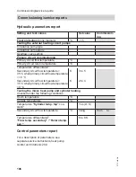
Page 106: ...w temperature 10 C K 3 to 5 Secondary circuit flow temperature 35 C when primary circuit flow temperature 0 C K 2 to 4 Testing the mixer heat pump and cylinder heating Checked under the following conditions Room temperature C Outside temperature C Temperature Cylinder temp top con stant Yes 1 K Secondary circuit flow temperature C rising from to Temperature differential ΔT Flow temp secondary Retu...

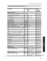
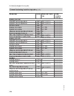
Page 107: ...l change over 7011 0 Operating status for external change over 7012 2 Effect of ext blocking on pumps com pressor 701A 0 Duration of external changeover 7013 8 h Effect of external demand on heat pump heating circuits 7014 4 Effect of ext blocking on heat pump heat ing circuits 7015 4 Vitocom 100 7017 0 Effect of external blocking on pumps compressor 701A 0 Common flow temperature sensor sys tem 7...

Page 108: ...e heat pump 6007 70 7 K Hysteresis DHW temperature booster heater 6008 100 10 K Start optimisation for DHW heating 6009 0 Stop optimisation for DHW heating 600A 0 Set DHW temperature 2 600C 600 60 C Temperature sensor at bottom of DHW cylinder 600E 0 Enable booster heaters for DHW heating 6014 0 Enable electric heaters for DHW heating 6015 1 Priority DHW heating with combi cylin der 6016 0 Start a...

Page 109: ...econdary pump 7340 Never adjust Heating water buffer cylinder Enable buffer cylinder low loss header 7200 0 Temp in operating status fixed value for buffer cyl 7202 500 50 C Hysteresis temperature heating buffer cylinder 7203 50 5 K Max temperature buffer cylinder 7204 600 60 C Temp limit op status fixed value for buf fer cylinder 7208 100 10 C Heating circuit 1 Standard room temperature 2000 200 ...

Page 110: ...educed room temperature 4001 200 20 C Remote control 4003 0 Heating curve level 4006 0 0 K Heating curve slope 4007 6 0 6 Influence room temperature hook up 400A 10 Room temperature hook up 400B 3 Max flow temperature heating circuit 400E 400 40 C Room temperature in party mode 4022 160 16 C Cooling Cooling function 7100 0 Cooling circuit 7101 1 Set room temperature separate cooling circuit 7102 2...

Page 111: ...0 Start wintertime week 7C05 5 Start wintertime day 7C06 7 Communication Heat pump number in cascade 5707 1 Enable LON communication module 7710 0 LON subscriber number 7777 1 LON fault manager 7779 0 Outside temperature 7797 0 LON system number 7798 1 Interval for data transfer via LON 779C 20 min Time via LON 77FF 0 Control Lock out controls 8800 0 Commissioning service reports Commissioning ser...

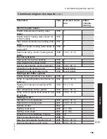
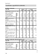
Page 112: ...temperature C 5 5 5 5 5 Heating water secondary circuit Contents l 227 28 7 38 7 53 5 57 1 Min flow rate spread 10 K l h 8000 10500 12900 15700 20700 Pressure drop at min flow rate mbar 100 100 100 100 120 Max flow temperature at min flow Primary circuit 5 C C 55 55 55 55 55 Max flow temperature at min flow Primary circuit 5 C C 60 60 60 60 60 Operation water water with intermediate circuit Type B...

Page 113: ...mbar 130 130 130 130 160 Max flow temperature C 60 60 60 60 60 Note Performance data to DIN EN 14511 corresponding to a temperature spread of 3 K at brine entry 0 C and brine outlet 3 C The flow rate is greater by a multiple factor than the specified minimum flow rate The test flow rate at ΔT 3 K corre sponds to 1 65 times the specified minimum flow rate The minimum flow rates are rounded up or do...

Page 114: ...V 50 Hz Fuse protection 1 x B16A Fuse MCB 6 3 AH slow 250 V Rated output W 1000 1000 1000 1000 1000 Max power consumption stage 1 W 25 25 25 25 25 Max power consumption stage 2 W 20 20 20 Max power consumption stages 1 stage 2 W 45 45 45 Safety category IP rating IP20 IP20 IP20 IP20 IP20 Refrigerant circuit Refrigerant R410A R410A R410A R410A R410A Refrigerant charge kg 23 5 29 9 34 5 45 0 60 5 Pe...

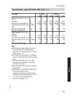
Page 115: ...20 1180 1240 1360 Sound emissions tested with reference to EN 12102 EN ISO 1914 2 Assessed total sound power level at B0 C 3 K W35 C 5 K At rated heating output dB A 61 5 63 63 64 65 Information regarding refrigerant The EC safety datasheet for R410A can be requested from the Technical Serv ices department of Viessmann Werke Specification type WW 1125 to WW 2300 Vitocal 300 W Pro installation and ...

Page 116: ...xample 2 Sketch for alternative hydraulic scheme Heating circuits fully installed and filled Electrical installation completed Hydraulic lines fully thermally insulated All windows and external doors sealed Geothermal probes well and connection lines fully installed Components for cooling mode fully installed option Preferred appointment 1 Date Time 2 Date Time All work ordered from Viessmann will...

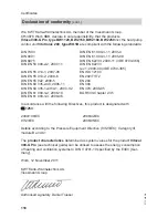
Page 117: ...5 2 40 2006 11 EN 394 DIN EN 60 335 1 with A1 2007 02 EN 378 2008 05 DIN EN 61 000 3 2 2006 10 BGR 500 Chapter 2 35 DIN EN 61 000 3 3 2009 06 In accordance with the following Directives this product is designated with _ 1253 2004 108 EC 2006 42 EC 97 23 EC 2006 95 EC Details according to the Pressure Equipment Directive 97 23 EC Category II module A1 The product characteristics determined as syste...

Page 118: ...IN EN 60 335 2 40 2006 11 EN 394 DIN EN 60 335 1 with A1 2007 02 EN 378 2008 05 DIN EN 61 000 3 2 2006 10 BGR 500 Chapter 2 35 DIN EN 61 000 3 3 2009 06 In accordance with the following Directives this product is designated with _ 1253 2004 108 EC 2006 42 EC 97 23 EC 2006 95 EC Details according to the Pressure Equipment Directive 97 23 EC Category III module B and C1 The product characteristics d...

Page 119: ...Connections 19 115 Hydraulic 42 Primary circuit 46 Secondary circuit 47 Connections main PCB 230 V components 52 Connection values Function components 54 Controller and sensor PCB 51 64 Control parameter reports 106 Control unit door 94 Cooling capacity 112 Cooling circuit flow temperature sensor Curve 93 Curve Temperature sensor type Pt 500 93 Temperature sensor type Ni 500 93 Cylinder primary pu...

Page 120: ...ow temperature sensor secondary cir cuit 92 Curve 93 Fuse MCB 114 Fuses MCB 51 H Heating cooling circuit Interface 35 Heating circuit pump 83 Heating water buffer cylinder Interface 35 Heat pump cascade Hydraulic connection 33 36 Higher output 10 High pressure sensor 91 High pressure switch 91 Hot gas temperature sensor 91 Hydraulic connections 42 Overview 42 45 Hydraulic installation scheme 2 sta...

Page 121: ...ource 86 On site components 82 Report 106 Swimming pool water heating 87 Parameter settings External functions 85 For DHW heating 37 For electric booster heater 86 For instantaneous heating water heater 86 For pumps and other components 83 Permiss operating pressure 114 Permissible operating pressure 78 Power OFF 71 Power supply 11 67 Pressure checking 79 Pressure drop 112 113 Primary circuit Brin...

Page 122: ...ting parameters 82 Soft starter 71 Solar thermal system 84 Starting current 114 Suction gas temperature sensor 91 Swimming pool 66 System flow temperature sensor Curve 93 System pressure checking 79 System scheme 87 System user instructing 88 T Temperature sensor type Pt 500 Curve 93 Temperature sensor type Ni 500 Curve 93 Terminating service 82 Tilting angle 14 Transport bracket 94 U Use of heat ...

Page 123: ...123 5772 458 GB ...

Page 124: ...98 7459199 Viessmann Limited Hortonwood 30 Telford Shropshire TF1 7YP GB Telephone 44 1952 675000 Fax 44 1952 675040 E mail info uk viessmann com Viessmann Werke GmbH Co KG D 35107 Allendorf Telephone 49 6452 70 0 Fax 49 6452 70 2780 www viessmann com 5772 458 GB Subject to technical modifications ...

Reviews: