49
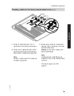
400 V~
230 V~
<42 V
1.
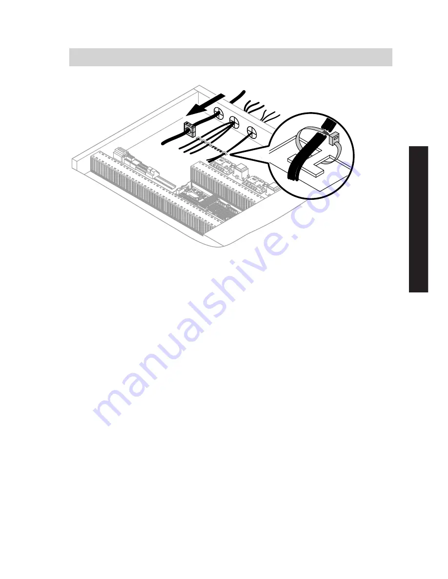
Route LV leads through "< 42 V"
opening to heat pump terminal area.
2.
Route 230 V cables through "230 V"
opening to heat pump terminal area.
Secure 230 V cables with cable ties.
Note
Route LV cables and 230 V cables as
far apart as possible.
3.
Route power cable for compressor
through "400 V" opening to the heat
pump terminal area.
Always
secure power cables with
strain relief fittings.
Note
Additional strain relief fittings are
required on site, as the wall clearance
≥ 80 mm.
For power supply, see from
page 67.
Installation sequence
Routing cables to the heat pump terminal area
(cont.)
5772 458 GB
Installation


