20
5608 487
v1.2
Vitocell 100-V Installation Instructions
Set-up and Connections
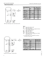
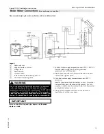
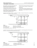
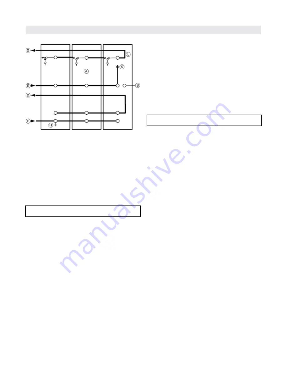
All piping reverse return or use balancing valves.
1. Pipe together boiler and tanks as illustrated.
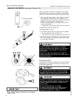
Connections must be accessible for service (use factory
supplied adaptors).
2. For boiler water supply temperatures over 203° F (95° C):
Remove plastic supply and return grommets (grommets
are left-threaded).
3. Pipe supply line with an incline and install an automatic
air vent at the highest point.
4. Install boiler sensor in sensor well (see pages 8 and 10).
5. Insulate piping.
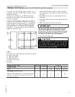
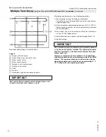
Legend
A
Group of DHW tanks
B
Sensor/Operating aquastat well
D
Boiler water return
E
Boiler water supply
F
Domestic cold water supply
G
Domestic hot water
H
Drain
K
Air vent
L
Secondary high limit aquastat location
IMPORTANT
IMPORTANT
The circulation pump is activated by the operating aquastat
or by the control system installed. The operating aquastat
should be mounted on the tank which receives the boiler
water supply last.
Viessmann recommends the installation of an additional
high limit aquastat in the main discharge pipe of the DHW
system. This aquastat should be wired in series with the
operating aquastat and should be set approximately 9° F
(5° C) higher than the operating aquastat.
Use Loctite 55 pipe sealing cord and pipe dope on all
threaded stainless steel nipples on tank.
Multiple Tank Set-up
[only for 79 and 120 USG (300 and 450 L) capacities]
(continued)
Recommended piping of multiple tanks

