background image

6

5608 487

  v1.2

Vitocell 100-V Installation Instructions 


Tank Connections

Set-up and Connections

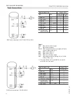
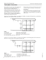
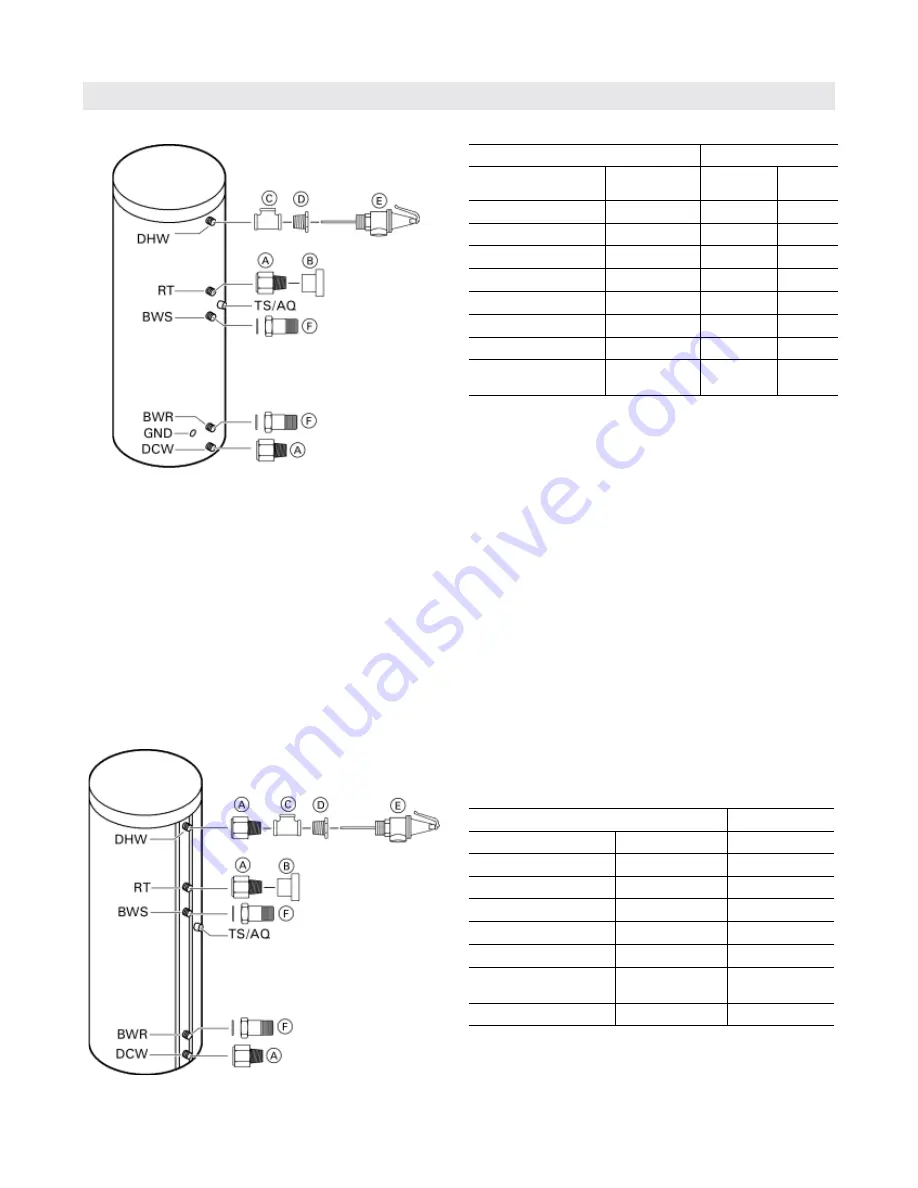
DHW tank connections 120 USG (450 L)

DHW tank connections 42 to 79 USG (160 to 300 L)

Legend

DHW 

Domestic hot water supply 

RT  

Recirculation tapping

TS/AQ  DHW temperature sensor or aquastat of boiler  


control (upper indirect coil)

BWS 

Boiler water supply 

*

1

BWR 

Boiler water return 

*

1

DCW 

Domestic cold water supply

GND 

Grounding connection (casing) 42 to 79 USG  


(160 to 300 L) only

*1

  The upper indirect coil is provided for connection 


to a boiler or a heat pump.

Supplied adaptor sizes

Vitocell 100-V

Part

Size

42/53 USG 

(160/200 L)

79 USG 

(300 L)

B

 Brass cap

c

 in.

1

--

A

 Brass adaptor

c

 in.

2

--

C

 Brass tee

c

 in.

1

--

F

 Brass adaptor

1 in. + gasket

2

2

B

 Brass cap

1


in.

--

1

A

 Brass adaptor

1


in.

--

2

C

 Brass tee

1


in.

--

1

Temperature and      

      pressure relief valve

c

 in.

1

1

Supplied adaptor sizes

Vitocell 100-V

Part

Size

120 USG (450 L)

B

 Brass cap

1 in.

1

A

 Brass adaptor

1 in.

1

A

 Brass adaptor

1

in.

2

C

 Brass tee

1

in.

1

D

 Reducer hex bushing

1

in. x 

in.

1

Temperature and      

      pressure relief valve

c

 in.

1

F

 Brass adaptor

1 in. + gasket

2

Summary of Contents for VITOCELL 100-V

Page 1: ...r future reference IMPORTANT CAUTION The heat transfer medium must be water or other non toxic fluid having a toxicity rating or class of 1 as listed in clinical toxicology of commercial products 5th edition This tank version is not suitable for steam heating applications The pressure of the heat transfer medium must be limited to a max of 30 psig by an approved safety or relief valve Please file ...

Page 2: ...mmencing installation Store documentation near product in a readily accessible location for reference in the future by service personnel uFor a listing of applicable literature please see section entitled Important Regulatory and Installation Requirements g Advice to owner Once the installation work is complete the heating contractor must familiarize the system operator ultimate owner with all equ...

Page 3: ...nstallation when using a Vitotronic 200 300 or Vitodens 200 10 Temperature sensor installation for solar operation using 120 USG 450 L tank 10 Levelling and bottom thermal insulation 11 Fitting the thermal insulating jacket 12 Fitting the thermometer and thermometer sensor if supplied and covers 13 Aquastat Installation when using a vitotronic 100 14 Boiler Water Connections heat exchanger connect...

Page 4: ...e of hot water heating systems There are no user serviceable parts on this equipment Ensure main power supply to equipment the heating system and all external controls has been deactivated Close main oil or gas supply valve Take precautions to avoid accidental activation of power during service work Safety Important Regulatory and Installation Requirements uPlease carefully read this manual prior ...

Page 5: ...This symbol indicates that additional pertinent information is to be found uThis symbol indicates that other instructions must be referenced WARNING Indicates an imminently hazardous situation which if not avoided could result in substantial product property damage serious injury or loss of life CAUTION Indicates an imminently hazardous situation which if not avoided may result in minor injury or ...

Page 6: ...SG 160 to 300 L only 1 The upper indirect coil is provided for connection to a boiler or a heat pump Supplied adaptor sizes Vitocell 100 V Part Size 42 53 USG 160 200 L 79 USG 300 L B Brass cap c in 1 A Brass adaptor c in 2 C Brass tee c in 1 F Brass adaptor 1 in gasket 2 2 B Brass cap 1 in 1 A Brass adaptor 1 in 2 C Brass tee 1 in 1 E Temperature and pressure relief valve c in 1 1 Supplied adapto...

Page 7: ...ess Rear in mm 18 460 Sides May be reduced if rear pipe connections can be reached with less clearance in mm 12 300 Top in mm 36 900 Front in mm 24 600 Minimum clearances to combustibles All sides in mm 0 0 Floor combustible CAUTION Install the DHW tank in a frost protected and draft free room Otherwise it must be drained when not in use in order to reduce the risk of damages caused by freezing IM...

Page 8: ...y insert sensor into metal clip on flange check anode connection on page 8 Install the insulation blanket and top cover IMPORTANT Do not extend the leveling bolts beyond an overall length of 1 in 35 mm Note For applications with Vitotronic 100 control use supplied plastic clip and two screws to secure Honeywell bulb capillary For applications with the Vitotronic 200 or 300 control option use suppl...

Page 9: ...ate the magnesium anode in the bottom flange lid from the grounding cable The magnesium anode may remain installed The temperature sensor for solar operation is included in the solar control unit package The brass elbow with sensor well is available as an option and must be used when solar connection is required 1 For solar operation install the sensor well into the brass elbow and connect the ass...

Page 10: ...r into sensor well 4 For applications with Vitotronic 100 control use supplied plastic clip and two screws to secure Honeywell bulb capillary For applications with the Vitotronic 200 or 300 control option use supplied plastic clip and two screws to secure sensor cable 5 to the tank sheet metal CAUTION Never wrap sensor with any type of tape or insulation Temperature sensor installation for solar o...

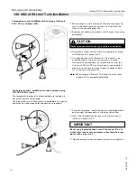
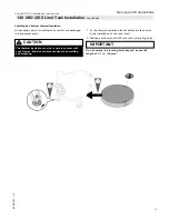
Page 11: ... DHW tank with its leveling bolts Levelling and bottom thermal insulation All necessary parts for enclosure assembly are packaged in a separate carton CAUTION The thermal insulation must not come in contact with open flames Exercise extreme caution when welding and soldering IMPORTANT Do not extend the leveling bolts beyond an overall length of 1 in 35 mm 120 USG 450 Liter Tank Installation contin...

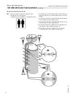
Page 12: ...lose to the tank Orient the jacket so the profile cutouts match the tank fittings 2 At the rear of the tank install all 6 clip closures evenly to both halves of the insulation jacket 3 At the front of the tank install all 6 clip closures evenly to both halves of the insulation jacket 4 At the rear of the tank tighten all 6 clip closures until both halves of the insulation jacket meet 5 At the fron...

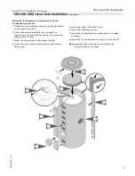
Page 13: ...e thermometer capillary tube through the front cover hole and insulation jacket then snap the thermometer in place 3 Insert the thermometer probe under the clip 4 Install the front cleanout cover and the front lower seam cover 5 Install the upper front seam cover 6 Install the back seam cover 7 Install the top insulation and press down the edges as shown 8 Install the top lid and press the logo A ...

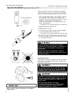
Page 14: ...w for mounting of aquastat Grounding connection Connect the grounding in accordance with the requirements stipulated by your local electricity supply company and current local regulations WARNING To ensure optimum safe operation the supplied stainless steel well must be installed The well diameter is large enough to accommodate a wide variety of sensing bulbs Always use spring clip to ensure prope...

Page 15: ...all a type tested high limit safety cut out if no other has previously been installed in this system For this purpose install a dual thermostat high limit thermostat and high limit safety cut out 4 Close off test nipples which are not used for the installation of a probe or sensor IMPORTANT Recommended piping for solar application with an additional tank Use a Loctite 55 string and pipe dope on al...

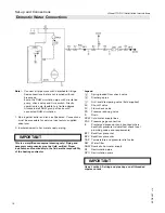
Page 16: ... supplied adaptors 2 Insulate domestic hot water supply piping Legend A Spring loaded flow check valve B Discharge pipe C Anti scald tempering valve field supplied SV Shut off valve FV Flow check valve PR Pressure reducing valve D Drain DCW Cold water supply lines PGC Pressure gage connection E Precharged expansion tank required where backflow preventer is installed check local plumbing codes and ...

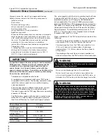
Page 17: ...local jurisdiction Backflow preventer Where backflow preventers are required a domestic water expansion tank installation is required in the cold water inlet piping before the cold water enters the tank The backflow device must be installed according to the manufacturer s installation instructions Observe local codes and regulations Tempering valve A tempering valve must be field installed where s...

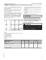
Page 18: ...ificantly in commercial applications during times when no or reduced demand for domestic hot water occurs Connection of a recirculation system in a multiple tank installation for systems utilizing boilers or remote heating plants without low temperature boiler return water Connection of a recirculation system in a multiple tank installation for remote heating plants with low temperature boiler ret...

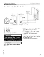
Page 19: ...r lines see illustration 3 Install boiler water supply and return header lines see illustration 4 Make final cold and hot water connections Both the boiler supply return header and the domestic hot cold water header must be installed in a reverse return method This ensures uniform heating of all tanks in the group Header sizes for batteries up to four 79 to 120 USG 300 to 450 L tanks are listed be...

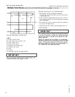
Page 20: ...urn E Boiler water supply F Domestic cold water supply G Domestic hot water H Drain K Air vent L Secondary high limit aquastat location IMPORTANT IMPORTANT The circulation pump is activated by the operating aquastat or by the control system installed The operating aquastat should be mounted on the tank which receives the boiler water supply last Viessmann recommends the installation of an addition...

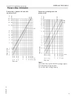
Page 21: ... Information Pressure drop on domestic hot water side secondary circuit Pressure drop on heating water side primary circuit Legend A 42 USG 160 L and 53 USG 200 L storage capacity B 79 USG 300 L storage capacities C 120 USG 450 L storage capacity Flow rate Pressure drop Flow rate Pressure drop ...

Page 22: ...arts Lists Operating and Service Instructions in the Service Binder 2 Install a protective hanging case near the boiler and store the Service Binder in this location For a listing of applicable Viessmann literature please see Important Regulatory and Installation Requirements on page 4 Inspection Opening Inspection opening for 79 USG 300 L tank Inspection opening for 120 USG 450 L tank ...

Page 23: ...23 5608 487 v1 2Vitocell 100 V Installation Instructions ...

Page 24: ...5608 487 v1 2 Technical information subject to change without notice Printed on environmentally friendly recycled and recyclable paper Vitocell 100 V Installation Instructions ...

Reviews: