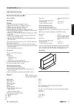
External control with a modulating burner
A
E
C
D
T6 T7 T8
90
41
L
B4
S3
T2
T1
N
41
B4
L
S3
N
T1
T2
STB
ON
TR
ON
TR
N
STB
B
A
Plug to the control unit
B
Burner base load
(floating contact for switching 230 V~)
C
T6, T7: Reduce burner output (modulation controller closed)
(floating contact for switching 230 V~)
D
T6, T8: Increase burner output (modulation controller open)
(floating contact for switching 230 V~)
E
Plug to the burner
Contact
B
at plug
aBÖ
closed Contact
B
at plug
aBÖ
open
Burner on (base load). The on-
site modulation controller regu-
lates the load-dependent modu-
lation. The boiler water tempera-
ture is restricted by the electronic
maximum temperature limiter.
Burner off.
Connection of on-site control units to EA1 extension in single boiler systems
Control via 0 – 10 V input:
External demand via 0 – 10 V input
Connection to the 0 – 10 V input on the
EA1 extension
.
In conjunction with a two-stage or modulating burner.
Code "01:1" for single boiler system (delivered condition).
U
+
L N
L
N
fÖ
S P
aBJ
Ö
[{{]
0-10V
f-]
A
+ -
The 0 - 10 V hook-up provides an additional set boiler water temper-
ature:
0 - 1 V is taken as "no default for set boiler water temperature".
1 V
≙
Set value 10 °C
10 V
≙
Set value 100 °C
The set default range can be changed in code 1E:
1 V
≙
Set value 30 °C
10 V
≙
Set value 120 °C
Note
Ensure DC separation between the negative pole and the earth con-
ductor of the on-site voltage source.
Digital data inputs DE1 to DE3
Functions:
■ External blocking
■ External blocking with fault message input
■ Fault message input
The hooked-up contacts must correspond to safety category II.
Input function assignment
Select the input functions via the codes on the boiler control unit:
■ DE1: Coding address "5d"
■ DE2: Coding address "5E"
■ DE3: Coding address "5F"
Set flow temperature for external demand
■ The set flow temperature can be selected with code 9b.
Control units
(cont.)
88
VIESMANN
Gas condensing boilers
9
5822 449 GB


