54
5608 741 - 04
Vitodens Rigid and Flex Venting Systems Installation
Vent Requirements
(continued)
Single Pipe Venting (Room Air Dependent)
Combustion air supply
(continued)
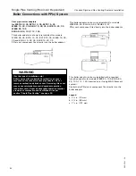
Inspect all finished exhaust vent/air intake piping to ensure:
Vent pipe and fittings are of approved material.
Acceptable size, length and number of elbows on
combined vent pipe system.
Installation is in accordance with prevailing provisions
of local codes.
Installation complies with the requirements of these
instructions, as well as the exhaust vent supplier’s
instructions.
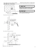
The exhaust vent system and terminations may be
installed in one of the following types of terminations:
1. Horizontal exhaust vent
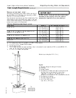
2. Vertical exhaust vent
CAUTION
Exposure to corrosive materials can cause heat
exchanger corrosion and failure.
CAUTION
Do not locate boiler in areas where high dust levels or
high humidity levels are present.
Note:
If above criteria are not properly observed and boiler
damage results, any warranty on the complete boiler
and related components will be null and void.
CAUTION
If the boiler has been exposed to high dust levels, all
burners and the heat exchanger must be cleaned prior
to use.
General Installation Information
The Vitodens boiler must be located in such a way that
the vent length is as short as possible and that the vent
can be routed as directly (and with as few bends) as
possible.
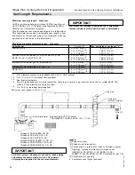
The minimum equivalent vent length is 4 ft. (1.2 m).
See table on page 66 and 67 for maximum vent lengths.
All products of combustion must be safely vented to the
outdoors.
All Vitodens boilers vent under positive pressure and are
Category IV boilers.
WARNING
Failure to provide an adequate supply of fresh
combustion air can cause poisonous flue gases to
enter living space, which can cause severe personal
injury or loss of life.
Viessmann recommends that the entire vent system be
checked by a licensed professional heating contractor at
least once each year following initial installation.
The remaining space surrounding a chimney liner, gas
vent, or special gas vent or plastic piping installed within
a masonry, metal or factory-built flue shall not be used
to supply combustion air.
The stainless steel special venting system is completely
sealed when fully assembled. Locking bands are used to
reinforce the joints between pipe and fittings.
WARNING
Different manufacturers offer a number of different
joint systems and adhesives. Do not mix pipes, fittings
and/or joining methods from different manufacturers.
Failure to comply could result in leakage, potentially
causing personal injury or death.
Do not install vent pipe such that flue gases flow
downwards. The direction of flue gas flow must be
vertically upwards or horizontal with an upward slope.
Ensure there is no flue gas leakage into the area in which
the boiler is installed.
Check joints for leaks with the gas supply turned off and
the fan running. Use a soapy solution to check for vent
leaks.
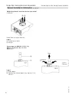
Condensate must drain from the flue pipe to the boiler.
Ensure a suitable gradient of at least 3º [approx. 2 in. per
3.3 ft. (50 mm per 1 m)].
No condensate trap is required in the vent pipe system.
*
Typically when the boiler is used as a temporary heat
source during the building construction phase.
CAUTION
Do not install boiler during construction involving
drywall or heavy dust of any kind. Dust can accumulate
in the burners and cause sooting. Install boiler after all
heavy dust construction is completed.
*


