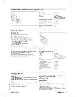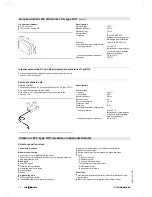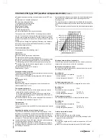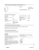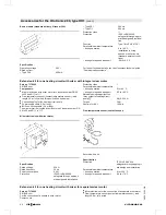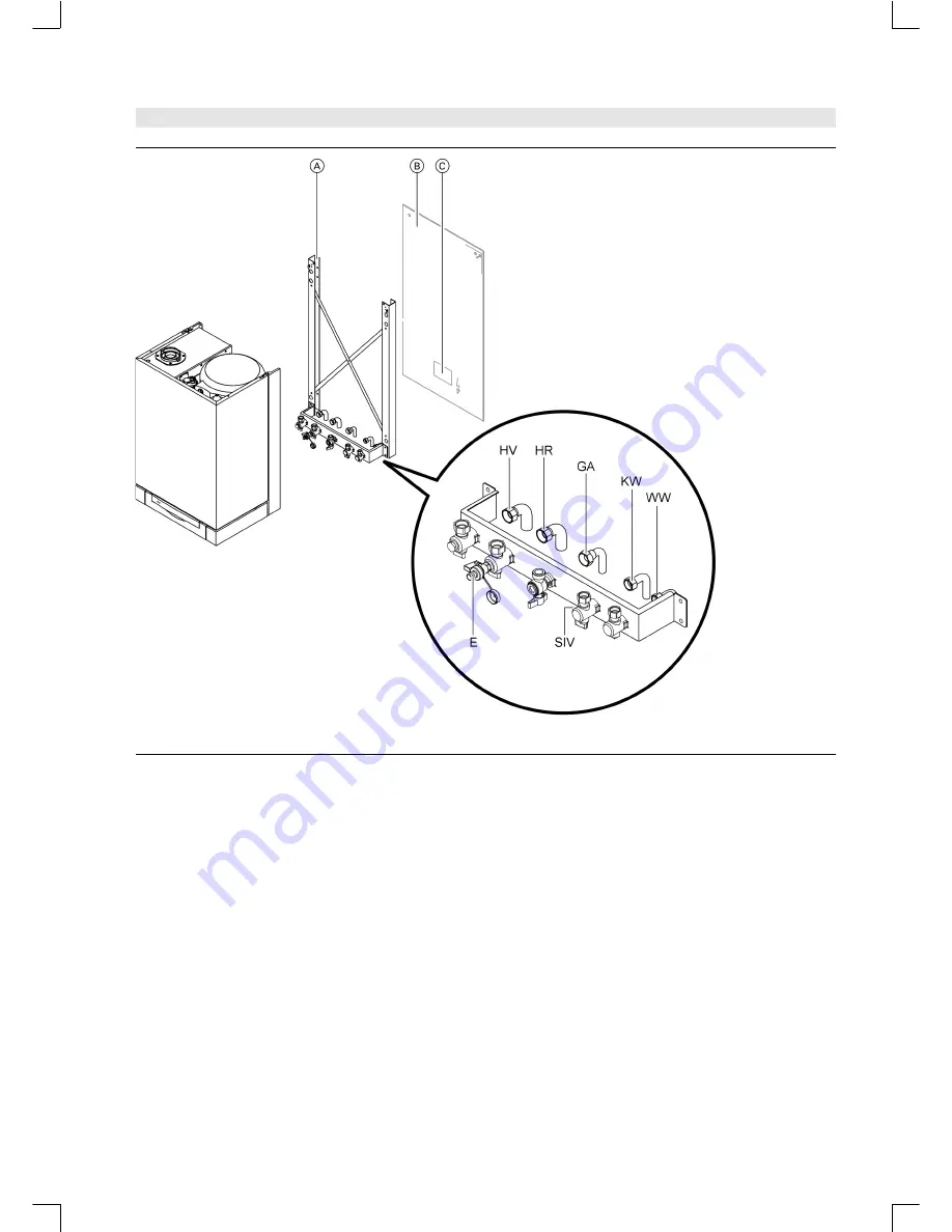
Mounting frame for finished walls
A
Installation template
B
Vitopend position
C
Area for electrical supply cables.
Allow all cables/leads to protrude approx. 1300 mm from the
wall.
E
Drain
GA Gas connection G ¾"
HR Heating return G ¾"
HV Heating flow G ¾"
KW Cold water G ½"
SIV Connection options for safety valve (secondary side)
WW Hot water G ½"
Note
For on-site connection dimensions for pipes, see page 14
5822
335-1
G
B
VITOPEND 222
VIESMANN
11
Pre-installation
(cont.)


