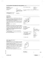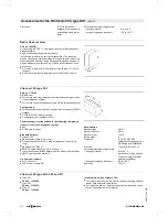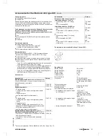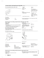
Power supply for accessories
The power supply of accessories can be connected directly to the
control unit. This connection is controlled with the system ON/OFF
switch (max. 4 A).
Where the boiler is installed in a wet area, the power supply con-
nection of accessories must not be carried out at the control unit.
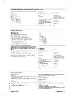
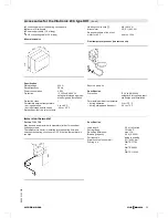
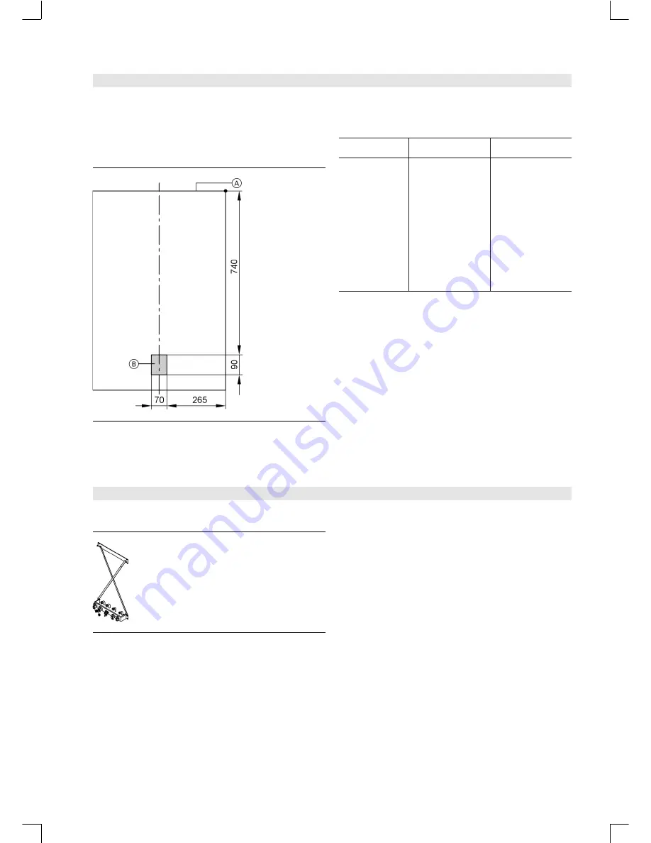
A
Reference point Vitopend top edge
B
Area for electrical supply cables
Allow all cables/leads to protrude approx. 1300 mm from the wall
in area
B
.
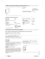
Cables
NYM-J
3 × 1.5 mm
2
2-core min.
0.75 mm
2
NYM-O 3 x 1.5 mm
2
–
Power supply
cables (also for
accessories)
–
Fault notification
–
External exten-
sion H1 and H2
(KM BUS)
–
Outside tempera-
ture sensor
–
Vitotronic 050
(LON)
–
Extension kit for
heating circuit with
mixer (KM BUS)
–
Vitotrol 100, type -
UTD
–
Vitotrol 200
–
Vitotrol 300
–
Vitotrol 100, type -
UTA
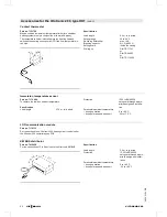
Interlocking circuit
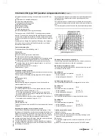
Install an interlock for open flue operation if required, if an extrac-
tor (e.g. cooker hood) is fitted in the room providing the boiler air
supply.
For this, the internal extension H2 (accessories) can be used.
This switches the extractors OFF when the burner is started.
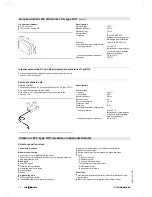
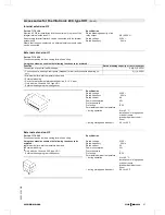
Accessories for Vitopend installation
Installation template for finished walls
Part no. 7186 957
&
Wall mounting fixture
&
Installation brace
&
Mounting panel with shut-off valves and boiler fill & drain valve
&
Pipe bends Ø 15/22
&
Gas stop cock G ¾"
Part no. 7186 958
&
Wall mounting fixture
&
Installation brace
&
Mounting panel with shut-off valves and boiler fill & drain valve
&
Pipe bends Ø 16/22
&
Gas stop cock G ¾"
Part no. 7186 959
&
Wall mounting fixture
&
Installation brace
&
Mounting panel with shut-off valves and boiler fill & drain valve
&
Pipe bends Ø 16/20
&
Gas stop cock G ¾"
5822
335-1
G
B
VITOPEND 222
VIESMANN
13
Pre-installation
(cont.)


