For a first approximation (cost estimate), an average temperature loss
of 1 K/day can be used. With an average pool depth of 1.5 m, an energy
demand of approx. 1.74 kWh/(d·m
2
pool surface area) is required to
maintain the set temperature. It is therefore sensible to use an
absorber area of approx. 0.4 m
2
per m
2
of pool surface.
Under the following conditions, never exceed the max. absorber area
stated in the table:
■ Design output of 600 W/m
2
■ Max. temperature differential between the swimming pool water
(heat exchanger flow) and the solar circuit return 10 K
Vitotrans 200, type WTT
Part no.
3003 453
3003 454
3003 455
3003 456
3003 457
Max. connectable absorber area Vitosol
m
2
28
42
70
116
163
18.2 Solar thermal system operating modes
Flow rate in the collector array
Collector systems can be operated with different specific flow rates.
The unit for this is the flow rate in l/(hm
2
). The reference variable is the
absorber area. At the same collector output, a higher flow rate means
a lower temperature spread in the collector circuit; a lower flow rate
means a higher temperature spread.
With a high temperature spread, the average collector temperature
increases, i.e. the efficiency of the collectors drops. On the other hand,
where the flow rates are lower, less energy is required to operate the
pumps and the pipework can be sized smaller.
Operating modes:
■
Low flow operation
Operation with flow rates up to approx. 30 l/(hm
2
)
■
High flow operation
Operation with flow rates greater than 30 l/(hm
2
)
■
Matched flow operation
Operation with variable flow rates
All operating modes are possible with Viessmann collectors.
Which operating mode is the right one?
The specific flow rate must be high enough to ensure a reliable and
even flow through the entire array. The optimum flow rate (relative to
the current cylinder temperatures and the current insolation level) in
systems with a Viessmann solar control unit will adjust itself automat-
ically in matched flow operation. Single array systems with Vitosol-F
or Vitosol-T can be operated without problems down to approx. 50 %
of the specific flow rate.
Example:
4.6 m
2
absorber area
Required flow rate: 25 l/(hm
2
)
This results in the following: 115 l/h, i.e. approx. 1.9 l/min
This value should be reached at 100 % pump rate. An adjustment can
be made at the output stage of the pump. The positive primary ener-
getic effect is lost if the required collector flow rate is achieved through
a higher pressure drop (= higher power consumption). Choose the
pump stage that lies above the required value. The flow rate is auto-
matically reduced via the control unit through a lower current supply to
the solar circuit pump.
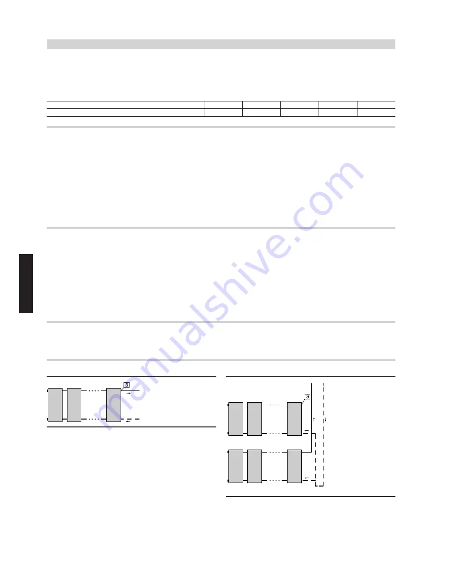
18.3 Installation examples Vitosol-F, type SV and SH
Take ventilation into consideration when designing the collector arrays
(see chapter "Ventilation" on page 151).
High-flow operation — single-sided connection
≤ 10
A
A
Collector temperature sensor in the flow line
≤ 10
≤ 10
A
A
Collector temperature sensor in the flow line
Information regarding design and operation
(cont.)
140
VIESMANN
VITOSOL
18
5822 440 GB


