background image

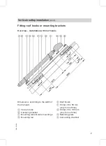
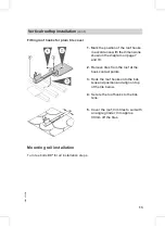
Fitting roof hooks for plain tile cover

1.

Mark the position of the roof hooks
in accordance with the dimensions
shown in the diagram on page 7
and 10.

2.

Remove tiles from the roof at the
hook contact points.

3.

Hook the roof hooks onto the bat-
tens and position and align on top
of the tile below.

4.

Secure the roof hooks to the bat-
tens.

5.

Cover the roof; trim tiles to suit with
an angle grinder; trim approx.
30 mm off the tiles.

Mounting rail installation

Turn tee bolts

90°

for all installation steps.

Vertical rooftop installation

(cont.)

13

5592

854

GB

Summary of Contents for Vitosol 300-T

Page 1: ...VIESMANN Installation instructions for contractors Vitosol 300 T Type SP3 Vacuum tube collector based on the heat pipe principle VITOSOL 300 T 5592 854 GB 3 2007 Dispose after installation...

Page 2: ...rried out by a qualified electrician Regulations Observe the following when working on this system all legal instructions regarding the prevention of accidents all legal instructions regarding environ...

Page 3: ...ber 16 Installation on flat roofs 17 Component overview 17 Determining the collector row distance z 18 Fitting the support frame 19 Fitting the mounting rails and connecting chamber 23 Hydraulic conne...

Page 4: ...lower part of the building in com pliance with VDE or local regula tions The connection of the collector sys tem to a new or existing lightning pro tection system or the provision of local earthing m...

Page 5: ...30 mm Slate cover 5 Roof hooks 6 Zinc plated countersunk chip board screw Spax s 6 x 30 mm Corrugated sheet cover 7 Roof hooks for corrugated roofing sheet profile 5 and 6 8 Roof hooks for corrugated...

Page 6: ...ing chamber qO Vacuum tube wP Locking rubber Accessories for one collector array wQ Connecting pipe wW Thermal insulation Connection set wE Connecting pipe short wR Connecting pipe long wT Locking rin...

Page 7: ...g to the width of the tile head A Vacuum tube B Clamping bracket C Mounting rail with tube mountings D Mounting rail E Roof hooks F Timber 38 x 58 mm only for roof tiles G Timber 30 x 100 mm only for...

Page 8: ...ting brackets e g on sheet steel roofs A Vacuum tube B Clamping bracket C Mounting rail with tube mountings D Mounting bracket E Mounting rail F Retaining plate G Connecting chamber Vertical rooftop i...

Page 9: ...Secure the mounting brackets to the substructure on site in accordance with the dimensions given in the dia gram on page 8 and 10 Vertical rooftop installation cont 9 5592 854 GB...

Page 10: ...roof hooks Note Centre the mounting rails maintain dimension f 81 mm Combination a mm b mm c mm d mm e mm 2 m2 850 3 m2 1260 2 m2 2 m2 850 1520 850 2370 670 2 m2 3 m2 850 1875 1260 2930 820 3 m2 3 m2...

Page 11: ...cordance with the dimen sions shown in the diagram on page 7 3 Hook the roof hooks into the timber in accordance with the dimensions shown in the diagram on page 10 4 Remove the drip tabs and protru s...

Page 12: ...ail instal lation on page 13 Fitting roof hooks for corrugated sheet cover 1 Mark the position of the roof hooks in accordance with the dimensions shown in the diagram on page 7 and 10 2 Position each...

Page 13: ...roof at the hook contact points 3 Hook the roof hooks onto the bat tens and position and align on top of the tile below 4 Secure the roof hooks to the bat tens 5 Cover the roof trim tiles to suit wit...

Page 14: ...ng brackets 1 Secure the mounting rails to the roof hooks or mounting brackets align vertically and horizontally 2 Align and fix the retaining plates to the mounting rails Vertical rooftop installatio...

Page 15: ...clamping brackets onto the mounting rails do not yet tighten the bolts 4 Click the mounting rails with tube holders into the clamping brackets align and fasten Note Tube holders on opposing rails mus...

Page 16: ...holders on the mounting rails must be in line with those in the connecting chamber where necessary align with a piece of string 3 Tighten the connecting chamber with the clamping brackets 4 Where sev...

Page 17: ...er and nut in pack 5 Front mounting bracket screw washer and nut in pack 6 Supports pre assembled with screws washers nuts and clamp ing brackets 7 Bracing rail qZ Mounting rail with tube mountings qI...

Page 18: ...tting Determining the collector row distance z When installing several collectors in series maintain distance z see page 20 Example W rzburg is located at approx 50 latitude 1 Determine the angle of t...

Page 19: ...Collector height Collector angle of inclination Angle of the sun Fitting the support frame Position the collector array as far south as possible linear tube axis aligned east west Installation on flat...

Page 20: ...ot A B Foot B Combination a mm b mm 2 m2 2 m2 900 900 620 2 m2 3 m2 900 1200 824 5 3 m2 3 m2 1200 1200 1029 1 Position feet A and B on a solid foundation in accordance with the dimensions on page 20 I...

Page 21: ...2 Secure the mounting brackets onto feet A and B according to the dimensions on page 20 Installation on flat roofs cont 21 5592 854 GB...

Page 22: ...art of the supports into the lower part to achieve the desired angle of inclination 7 Tighten the screws Fix the side bracing rails parallel to the mounting brackets Note The screw is no longer requir...

Page 23: ...ing brackets in accordance with the dimensions given in the diagram on page 20 and secure 2 Click the connecting chamber into the retaining plates and clamping brackets 3 Align the connecting chamber...

Page 24: ...e continue with Connecting the connecting chamber on page 24 otherwise continue with Fitting the connec tion set on page 25 Hydraulic connections Linking the connecting chamber A Nut for the retaining...

Page 25: ...collector connectors 5 Align and secure the connecting chamber see page 23 6 Cut the thermal insulation linearly fit it and join its cut faces with adhe sive Fitting the connection set Observe the fol...

Page 26: ...retaining clips click clips into the groove in the connect ing pipes through the holes in the collector connectors 5 Thread the locking ring fittings onto the connecting pipe 6 Insert the support slee...

Page 27: ...lector temperature sensor Danger The vacuum tubes can become hot and break if insufficient care is taken This can lead to burns and injuries Wear gloves and safety gog gles A Dual pipe heat exchanger...

Page 28: ...rber towards the sun Ensure that no part of the ther mal insulation is pinched The surface of the condenser must be clean The condenser must be posi tioned centrally inside the heat exchanger retainer...

Page 29: ...temperature resistant sealants e g Viscotex Solarpaste from Locher CH 9450 Altst tten Switzerland Never step onto solar panels Never solder near or on the collector 1 Position pipes so that complete...

Page 30: ...ns pressure and temperature resistant observe the max idle temperature of the collec tor A Collector B Solar Divicon C Drip container D Expansion vessel E Pre cooling vessel F Shut off valve G Filling...

Page 31: ...For commissioning of the solar heating system see the Vitosol service instructions Commissioning and adjustment 31 5592 854 GB...

Page 32: ...B Subject to technical modifications Viessmann Werke GmbH Co KG D 35107 Allendorf Telephone 49 6452 70 0 Fax 49 6452 70 2780 www viessmann com Viessmann Limited Hortonwood 30 Telford Shropshire TF1 7Y...

Reviews: