background image

12

6167196 GB

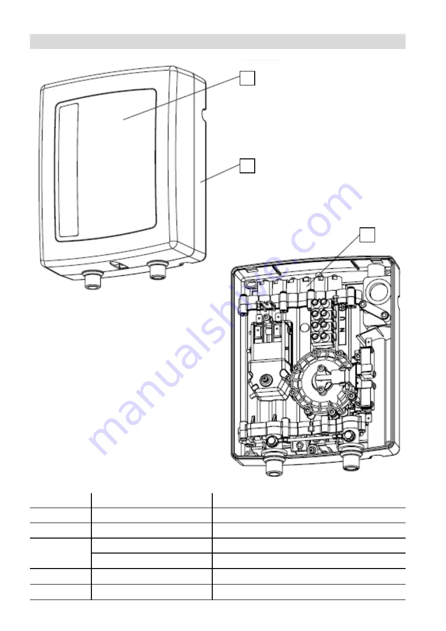
Structure of the instantaneous water heater

Maintenance

Position

Service code

Description

1

7857222

Front casing EI3 EI5

2

7857721

Back panel EI3 EI5

3

7857719

Heat exchanger, complete EI5 3.5 kW

7857720

Heat exchanger, complete EI5 5.5 kW

4

7877983

Power cable EI5.A3 GB

5

7877980

Power cable EI5.A5 GB

3

2

1

Summary of Contents for VITOTHERM EI5 Series

Page 1: ...Vitotherm EI5 Version EI5 A3 K Version EI5 A5 K Electric instantaneous water heaters Please retain for future use Installation and service instructions for contractors VITOTHERM EI5 6167196 GB 11 2020 ...

Page 2: ...tions for environmental protection Codes of practice of the relevant trade associations Regulations to be observed Work on electrical equipment must only be carried out by a qualified electrician The system must be commissioned by the system installer or a qualified person authorised by the installer Relevant safety regulations Requirements stipulated by the local power supply utility Requirements...

Page 3: ...ons to the water or electrical installations Do not make any structural modifications to the appliance Maintenance work Only install the appliance on a suitably stable wall with the fixing materials provided Do not make any structural modifications to the appliance Install an isolator in the power cable to provide omnipolar separation from the mains for all active conductors corresponding to overv...

Page 4: ... For appliances with a power cable use only original Viessmann spare parts For your safety cont Safety instructions Danger If there are leaks in the appliance there is a risk of electric shock Isolate the appliance from the power supply e g At the separate fuse or by means of a mains isolator Close the cold water supply shut off valve Safety instructions for operating the device If water escapes f...

Page 5: ...with inlet and outlet pipes at the top of the appliance 8 Connection and wiring diagram 9 Wiring diagram for type EI5 A3 K 9 Connection diagram for type EI5 A3 K 9 Wiring diagram for type EI5 A5 K 10 Connection diagram for type EI5 A5 K 10 3 Maintenance Operation 11 Venting 11 Maintenance 11 Structure of the instantaneous water heater 12 Removing the complete heating module 13 4 Appendix Specifica...

Page 6: ... can supply one or more draw off points as applicable The appliance is intended for domestic use It can be operated safely by untrained persons The appliance can also be used in a non domestic environment e g in a small business as long as it is used in the same way Any use that differs from or goes beyond this is considered inappropriate Intended use also extends to compliance with these instruct...

Page 7: ...r 8 Ensure that live parts cannot be touched through the openings on the back of the appliance 9 Switch on the power supply Check that the appliance is working correctly Prepare the water pipes and the electric cables according to local regulations and connect to the appliance 1 Remove the cover from the appliance Undo the screw Remove the cover starting on the side with the connections 2 Secure t...

Page 8: ...n cont Installation sequence Flow limiter EI5 A3 K Black 1 9 l min EI5 A5 K Violet 3 4 l min Assembly with inlet and outlet pipes at the bottom of the appliance Assembly with inlet and outlet pipes at the top of the appliance ...

Page 9: ...sure switch BV Differential pressure switch Q1 Q2 Switching contacts of differential pressure switch E1 Heating module X1 Power cable Wiring diagram for instantaneous water heater EI5 A3 K Connection diagram for instantaneous water heater EI5 A3 K Outlet connector Inlet connector ...

Page 10: ...ressure switch BV Differential pressure switch Q1 Q2 Switching contacts of differential pressure switch E1 Heating module XP Power cable Wiring diagram for instantaneous water heater EI5 A5 K Connection diagram for instantaneous water heater EI5 A5 K Outlet connector Inlet connector ...

Page 11: ...Switch on the power supply Maintenance 1 Switch off the power supply e g at the separate fuse or a mains isolator 2 Close the shut off valve in the cold water supply pipe 3 Undo cold water supply pipe on appliance Water may leak out when doing so 4 Remove the filter from the cold water supply pipe 5 Clean the filter and reinstall it in its original position 6 Fit cold water supply pipe on applianc...

Page 12: ...intenance Position Service code Description 1 7857222 Front casing EI3 EI5 2 7857721 Back panel EI3 EI5 3 7857719 Heat exchanger complete EI5 3 5 kW 7857720 Heat exchanger complete EI5 5 5 kW 4 7877983 Power cable EI5 A3 GB 5 7877980 Power cable EI5 A5 GB 3 2 1 ...

Page 13: ...13 6167196 GB Removing the complete heating module 2 Press both locks simultaneously 1 Remove front cover Maintenance ...

Page 14: ...14 6167196 GB Removing the complete heating module cont Maintenance 3 Tilt the heating module forwards at an angle of 30 4 Pull the heating module out of the top locks ...

Page 15: ...Power consumption A 14 5 22 7 Flow rate at Δt 30 K l min 1 5 2 4 Flow pressure MPa 0 12 0 6 Start flow rate l min 1 2 2 0 Dimensions height x width x depth mm 225 x 170 x 75 Weight kg 1 2 Min cable cross section mm2 3 x 1 5 3 x 2 5 Max permissible mains impedance Ω 0 31 Min flow resistance at water temperature 15 C Ωcm 1100 Water connection male thread G 3 8 distance between inlet and outlet 80 mm...

Page 16: ...rrect disposal of the product prevents potentially harmful effects on the environment which can occur due to the improper handling of waste For more information on recycling this product please contact your local government a waste disposal service or the store where this product was purchased Copyright Viessmann Poland The reproduction copying or use of this document or parts thereof without the ...

Reviews: