13
R1 L`
N
R4
R4
L` L
R2
R3
A
N
L
?
B
C
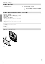
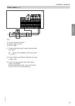
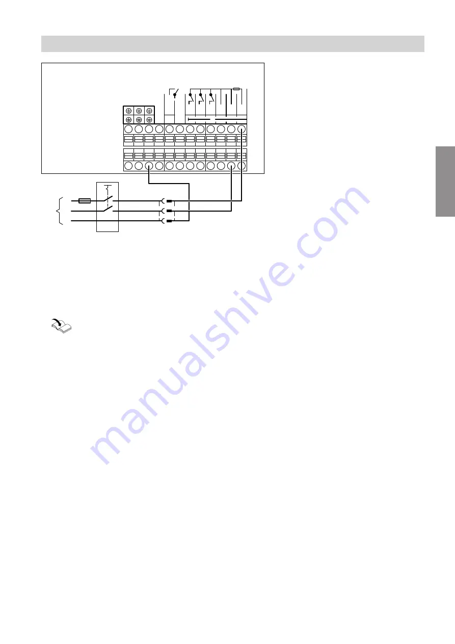
Fig.9
A
Control unit wiring chamber
B
Mains isolator (on site)
C
Power supply
1.
Check whether the system has been flushed, filled
and vented.
Vitotrans 353 installation and service instruc-
tions
2.
Check whether all electrical connections have been
correctly made.
3.
Connect the power cable in the control unit as
shown in the diagram.
Recommended power cable: 3-core with a cross-
section of 0.75 mm
2
with standard plug
Installation sequence
Power supply
(cont.)
5517 095 GB
Installation
Summary of Contents for VITOTRANS 353
Page 50: ...50 5517 095 GB ...
Page 51: ...51 5517 095 GB ...


