7
VFS/US
0-10V
PWM1
22
V40
S10
20
19
S9
18
17
0-10V
PWM2
24
0-10V
PWM1
22
0-10V
PWM3
26
0-10V
PWM4
28
30
32
31
+VBus-
2
1
S1
4
3
S2
6
5
S3
8
7
S4
10
9
S5
12
11
S6
14
13
S7
16
15
S8
Temp. Sensor
Flow Rotor
1
1
1
1
R1
L`
N
R4
R4
L`
L
R2
R3
B
A
C
D
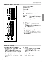
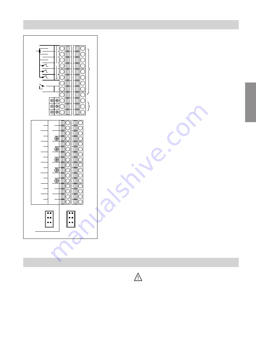
Fig.2
A
Control unit wiring chamber
B
Fuse 4 A (slow)
C
Terminals, neutral conductors
D
PE terminals
230 V connections
R1 to R3 Semi-conductor relay
(R1 to R3 suitable for speed control)
R4
Potential-free relay
LV terminals
VBus
VBus to connect the control units in
a cascade
PWM1 to PWM4 PWM signals for pumps at R1 to R3
S1 to S8
Temperature sensors
Routing cables
!
Please note
Contact with hot components causes cable
damage.
After installation, cables must not come into con-
tact with hot components.
■
Types PBS, PBM and PBL:
Route cables to the outside through the rear thermal
insulation (cut-out in the upper part).
■
Types PZS and PZM:
Route the cables through the hole for the return on
the heating water side (in the support panel and the
rear thermal insulation).
Connecting the pumps
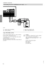
Pump to be connected, individual appliance:
■
Secondary pump (DHW circulation pump) from the
DHW circulation set, accessories
Connect the connecting cable to the pump using
plugs and connect in the control unit; see diagram.
Pump to be connected, cascade:
■
Secondary pump (DHW circulation pump), accesso-
ries
Recommended cable: 3-core with a cross-section of
0.75 mm
2
Danger
Incorrect core allocation can result in serious
injury and damage to the appliance.
Take care not to interchange cores "L'", "R2"
and "N".
Colour coding to IEC 60 757:
BN
Brown: L' and PWM2 24
BU
Blue: N and PWM2 PE
GNYE Green/yellow: PE
Installation sequence
Overview of electrical connections
5517 095 GB
Installation
Summary of Contents for VITOTRANS 353
Page 50: ...50 5517 095 GB ...
Page 51: ...51 5517 095 GB ...


