background image

Electrical connections

16

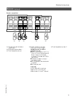
Pumps

(accessory)

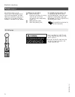
All circulation pumps can be
“hard-wired” to the terminal strip of
the Power Pump Module. Pre-wired
Viessmann circulation pumps can be
plugged into the respective Rast-5
terminals in the Power Pump Module.

Available pump connections

Boiler circuit pump
(heating circuit pumps for mixing
valve circuits 1 and 2 are
connected to the corresponding
actuator kit)
DHW production pump
DHW recirculation pump

For underfloor heating system only

An adjustable high limit must be
provided additionally. Install the fixed
high limit in the heating supply pipe

downstream

from the mixing valve and

the heating circuit pump.

See installation instructions for
the limit thermostat

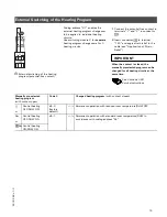
120 VAC pumps

1.

Insert supplied strain relief through
Power Pump Module knock-out and
fasten with nut.

2.

Connect the Rast-5 connector to the
respective plug-in terminal on the
Power Pump Module.

5

3

0

3

2

6

9

v

1

.3

ONLY Viessmann pre-wired (plug-in)
circulating pumps must be used. If
pre-wired pumps are used do not
connect an additional pump to the
respective “hard-wired” terminals.

WARNING

Summary of Contents for Vitotronic 300 KW3

Page 1: ...tions Vitotronic 300 Model KW3 Weather responsive indoor outdoor digital boiler control for heating systems with one or more heating circuits Part No Z001 231 Certified as a component part of Viessman...

Page 2: ...rtant Regulatory and Installation Requirements Advice to owner Once the installation work is complete the heating contractor must familiarize the system operator ultimate owner with all equipment as w...

Page 3: ...m with two heating circuits with mixing valves 7 Application Example 5 System with one direct connected heating circuit without mixing valve and two heating circuits with mixing valves 8 Electrical Co...

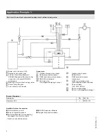
Page 4: ...tank temperature sensor KM BUS participants Extension for two stage modulating burner 1 Heating circuit pump Boiler circuit DHW production pump accessory DHW recirculation pump field supplied where r...

Page 5: ...recirculation pump installed on site Power supply 120 VAC 60 Hz Burner single stage 4 Burner two stage modulating 4 Required Equipment Description Qty Part No Vitotronic 300 1 Z001 231 Mixing valve ac...

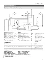
Page 6: ...cuit pump 2 DHW production pump accessory DHW recirculation pump field supplied where required Power supply 120 VAC 60 Hz Burner single stage 4 Burner two stage modulating 4 Required Equipment Descrip...

Page 7: ...rcuit pump 2 DHW production pump accessory DHW recirculation pump field supplied where required Power supply 120 VAC 60 Hz Burner single stage 4 Burner two stage modulating 4 Required Equipment Descri...

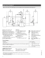
Page 8: ...Mixing valve circuit pump 2 Heating circuit pump DHW production pump accessory DHW recirculation pump field supplied where required Power supply 120 VAC 60 Hz Burner single stage 4 Burner staging tak...

Page 9: ...pump module Do not connect any external equipment directly Low voltage connectors Outdoor temperature sensor Boiler temperature sensor DHW tank temperature sensor 1 BDHW tank temperature sensor 2 Flu...

Page 10: ...ating of 15 A L and N L LINE N Neutral G Ground This equipment must be grounded Ensure that the following wires are not interchanged WARNING 120 VAC 60 Hz 1 Ph Power supply Provide 15 A overcurrent pr...

Page 11: ...ater cut off device typical 11 Vitotronic Connections continued Low water cut off connections 1 Run 3 conductor cable between low water cut off device and Power Pump Module 2 Remove jumper on Power Pu...

Page 12: ...of strain relief clamp 3 Insert the cable in the bushing and secure the wires to the plug in connector Insert bushing in clamp and connector in socket 4 Fasten top portion of strain relief clamp No a...

Page 13: ...ered wall allow room for plaster or remove sensor before plastering wall 1 Remove sensor housing 2 Secure wall mount base to wall cable inlet opening to the bottom 3 Pass cabling through openings in t...

Page 14: ...rol unit Heating systems with domestic hot water heating 1 Install the DHW tank temperature sensor Installation Instructions for domestic hot water tank When installing the DHW tank temperature sensor...

Page 15: ...or north western wall 2 to 2 5 m 6 5 to 8 ft above ground level in case of multi storey buildings in the upper half of the second floor Not above windows doors or ventilation outlets Not immediately...

Page 16: ...r underfloor heating system only An adjustable high limit must be provided additionally Install the fixed high limit in the heating supply pipe downstream from the mixing valve and the heating circuit...

Page 17: ...ter The Vitotronic 300 is prewired with the Viessmann quick connect plug in system 1 Connect the RAST 5 plug in connector to the main circuit board of the control 2 Connect 7 pole plug to the counter...

Page 18: ...ol unit burner p Signal direction Burner control unit The connection is made via the extension for 2 stage modulating burner See Installation Instructions for boiler and extension for 2 stage modulati...

Page 19: ...ly strain relief to the cable see Application of Strain Relief When the contact is closed the manually preselected program can be changed for all heating circuits at the same time See Vitotronic 300 S...

Page 20: ...to the rear 4 Turn slotted screw on the rear of the fixed high limit and set to 212 F 100 C once adjusted the fixed high limit cannot be reset to 230 F 110 C 5 Put front panel cover and fuse back in...

Page 21: ...ixed High Limit contd Adjustment to 100 C JUMO The fixed high limit is factory preset to 230 F 110 C 5303 269 v1 3 2 1 4 3 5 6 If adjusted to 212 F 100 C do not set the adjustable high limit above 167...

Page 22: ...rn the selector knob fully clockwise 4 Check the box in the Vitotronic 300 Service Instructions to confirm that the adjustment was made If the system is operated in conjunction with a domestic hot wat...

Page 23: ...e holding clip at the bottom of the control 5 Insert the flat cable connector in plug in location X10 and lay cable under holding clip 6 Unlock hinged support bar by applying pressure to linkage point...

Page 24: ...ns regarding start up and settings Service document ring binder 1 File Installation Operating and Service Instructions in service binder 2 Service box optional equipment now available for service bind...

Page 25: ...Appendix 25 5303 269 v1 3...

Page 26: ...Appendix 26 5303 269 v1 3...

Page 27: ...Appendix 27 5303 269 v1 3...

Page 28: ...smann ca mail viessmann ca Viessmann Manufacturing Company U S Inc 45 Access Road Warwick Rhode Island 02886 USA Tel 401 732 0667 Fax 401 732 0590 www viessmann us com mail viessmann us com 28 Printed...

Reviews: