25
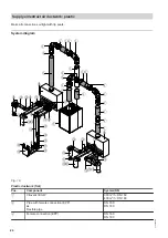
Pos.
Component
System/DN
5
Mounting bracket
DN 160
DN 180
6
90° bend with female connection (EPP), can be split into 2 x
45° bends
DN 160
DN 180
9
Silencer, round, flexible
DN 160
DN 180
qP
Air distribution box with cap
DN 160/system 100
DN 180/system 100
Restrictor
System 100
qW
Lip seal
System 100
qE
Flat duct, flexible
System 100
qR
Flat duct:
90° bend, narrow side
System 100
qT
Diverter
System 100/DN 125
qZ
Supply air valve for setting into a wall or ceiling (plastic)
or
DN 125
Supply air valve with mounting ring (metal)
qU
Flat duct:
90° bend, broad side
System 100
qI
Connection piece
System 100
qO
Floor outlet
System 100
wP
Floor vent grille
—
wQ
Extract air valve for setting into a wall or ceiling (plastic)
or
DN 125
Extract air valve with mounting ring (metal)
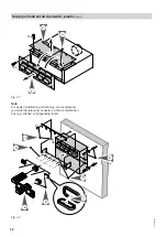
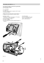
Restrictors for adjusting the air flow rate
Calculate the flow rate and pressure drop with the aid
of the calculation program (download from
www.viessmann.de)
prior
to installation.
Individual rings are knocked out of the restrictors to
adjust the flow rate. How many rings need to be
knocked out depends on the pressure drop calculation.
1
2
3
4
Fig. 20
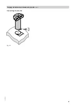
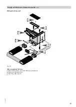
Connecting the air distribution box
Flat duct connectors may be mounted forwards or
turned 90°.
Supply air/extract air ductwork: plastic
(cont.)
5793 589 GB


