37
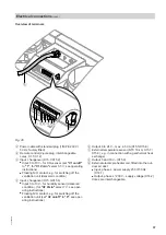
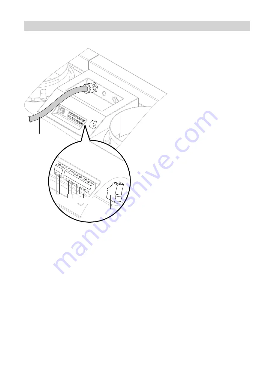
Overview of terminals
A
+
-
+
-
+
-
H
D F
C
B
E G
Fig. 36
A
Power cable with standard plug (1/N/PE 230 V/
50 Hz, factory fitted)
B
Remote control (2-pole plug, interchangeable
cores, X1.1/X1.2)
C
Input, changeover (X15.1/X15.2)
■
Input 0 to 10 V
–
for CO
2
sensor (set
"V1 on/off"
to
"1"
, for
"V1 Vmin"
select 3.5 V; see operating
instructions)
■
Floating N/O contact, e.g. for switching off the
ventilation unit (delivered condition)
D
Input, changeover (X15.3/X15.4)
■
Input 0 to 10 V
–
for humidity sensor (delivered
condition), (for
"V2 Vmin"
select 7 V; see oper-
ating instructions)
■
Floating N/O contact, e.g. for switching off the
ventilation unit (set
"V2 on/off"
to
"0"
; see oper-
ating instructions)
E
Output 0 to 24 V
–
, max. 4.5 VA (X15.5/X15.6)
F
External temperature sensor (NTC 10 k
Ω
, X15.7/
X15.8), e.g. in connection with a geothermal heat
exchanger
G
Output 0 and 10 V
–
(X15.9)
H
External electric preheater coil, fitted into the out-
door air duct
■
Input, phase L: power supply 230 V/50 Hz
(X14.1)
■
Output, phase L': 230 V~ supply voltage (X14.2)
Cores are interchangeable.
Electrical connections
(cont.)
5793 589 GB


