background image

25

Troubleshooting

Faults which are displayed at the programming unit

(cont.)

Plain text fault display

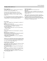
Outdoor temperature sensor

Supply sensor

DHW Tank sensor 1 or 2

Will only be displayed if a second DHW tank temperature

sensor is connected.

Sensor 17B

Room temperature sensor

Collector sensor

Solar DHW sensor

Participant number

Fault – participant

Display only if the control unit is programmed as fault

manager.

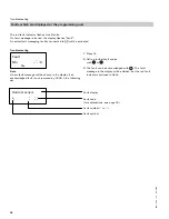
Calling up acknowledged fault messages
1.

Press

for approx. 2 seconds.

The fault will then be displayed.

2.

Select an acknowledged fault
with

or

.

Fault
code

System characteristics

Cause

Remedy

10

Activates after 0 °C / 32 °F
outdoor temperature

Short circuit
Outdoor temperature sensor

Check outdoor temperature sensor
(see page 39)

18

p

Open circuit
Outdoor temperature sensor

(

p g

)

20

Mixing valve is ”Closed”

Short circuit
Supply temperature sensor
Mixing valve circuit M1

Check supply temperature sensor
(see page 38)

28

Open circuit
Supply temperature sensor
Mixing valve circuit M1

40

Short circuit
Supply temperature sensor
Mixing valve circuit M2

44

Short circuit
Supply temperature sensor
Mixing valve circuit M3

48

Open circuit
Supply temperature sensor
Mixing valve circuit M2

4c

Open circuit
Supply temperature sensor
Mixing valve circuit M3

5581

529

v1.0

08/2006

Summary of Contents for Vivotronic 050 HK1S

Page 1: ...ons for the contractor Vitotronic 050 Model HK1S and HK3S Outdoor re set mixing valve control Certified as a component part of Viessmann boilers only Vitotronic 050 Typ HK1S Vitotronic 050 Typ HK3S Pl...

Page 2: ...anty Information contained in this and related product documentation must be read and followed Failure to do so renders warranty null and void Advice to owner Once work is complete the heating contrac...

Page 3: ...ting curves 17 Service scans Service level summary 20 Temperatures and quick scans 21 Scanning operating conditions 23 Troubleshooting Faults which are displayed at the programming unit 24 Downloading...

Page 4: ...ng circuit pump sA DHW tank pump sK DHW re circulation pump f Power supply 120V 60 Hz gS Mixing valve motor aVD External connections see page 11 aVG KM BUS Participant Coding For systems with a DHW ta...

Page 5: ...r aJB Return temperature sensor s M2 M3 Heating circuit pump Primary pump sA DHW tank pump sK DHW re circulation pump f Power supply 120V 60 Hz gS Mixing valve motor aVD External connections aVG KM BU...

Page 6: ...Installation Module Installation A1 Power supply module A2 Electronic module A3 Power module A4 Extension module 1 Modules pre installed in Vitocontrol C panel 2 For connections see page 10 5581 529...

Page 7: ...7 Installation Summary of electrical connections HK1S 5581 529 v1 0 08 2006...

Page 8: ...8 Installation Summary of electrical connections cont HK3S 5581 529 v1 0 08 2006...

Page 9: ...nd control unit back 1 Opening on front of Vitocontrol C is 305 x 129 mm 12 x 5 inches 2 Frame and socket 3 User interface 4 Connect the control to electronic module connection X10 5581 529 v1 0 08 20...

Page 10: ...xing valve actuator connection Used For Mixing valve actuator heating circuit M1 on Module A3 Mixing valve actuator heating circuit M2 M3 on module A4 For mixing valve actuator connections see job spe...

Page 11: ...91 and 9A External Mixing valve closed Closing the contact closes the mixing valve Allocation to the heating circuits via coding address 99 The function mixing valve closed has priority over mixing va...

Page 12: ...m up DHW re circulation pump time program j Holiday program tw DHW temperature tm Reduced room temperature n Heating curve slope N Heating curve level u Time date 9 Standby mode w DHW only rw Heating...

Page 13: ...stem cable to LON connection on module A2 Note Data transfer via the LON system can take several minutes Setting up LON participant numbers In code 1 via coding address 77 In a LON system the same num...

Page 14: ...via LON Set code 81 3 Time received via LON fixed Receive outdoor temperature via LON Code 97 2 Outdoor temperature is received via LON Set code 97 1 Outdoor temperature is received via LON Set code 9...

Page 15: ...nations of the selected user flash for approx 60 seconds During communication between both devices Check OK flashes Check not OK flashes if there is no communication between both devices Check the LON...

Page 16: ...HW re circulation pump ON Heating circuit pump M2 ON Heating circuit pump M3 ON Mixing valve M2 OPEN Mixing valve M2 CLOSED Mixing valve M3 OPEN Mixing valve M3 CLOSED Fault messaging ON Notes The ill...

Page 17: ...t simply The lower the outdoor temperature the higher the supply temperature The room temperature again depends on the supply temperature Settings in the factory default setting Slope n 1 4 Shift N 0...

Page 18: ...ng the maximum limit for the supply temperature for each heating circuit separately Factory default setting 75 C 167 F change via coding address C6 Note For underfloor heating circuits you can select...

Page 19: ...room temperature from 20 C to 26 C 68 F to 79 F Example 2 Adjustment of the reduced room temperature from 5 C to 14 C 41 F to 57 F ASupply temperature in C F BOutdoor temperature in C F CSet room temp...

Page 20: ...rw buttons simultaneously for approx 2 seconds Press OK 21 Operating condition Press L Press L 23 Troubleshooting Press L Press OK 24 Calling up acknowledged fault messages Press OK for approx 2 secon...

Page 21: ...utdoor temp actual Sensor 17 B Set DHW temp Actual DHW temp DHW Temp 1 actual DHW temp 2 actual Supply temperature set Supply temperature actual Room temp set Room temp actual Quick scan 1 to Quick sc...

Page 22: ...trol Mixing valve circuit M2 N A ystem no N A N A 8 N A N A Operating mode Mixing valve circuit M2 0 w o remote control 1 with Vitotrol 200 2 with Vitotrol 300 Subnet address sys Software version Neur...

Page 23: ...emperature set value Actual room temperature Actual solar DHW temperature Collector temperature actual value Time Date Output 20 ON OFF Output 52 OPEN CLOSED DHW Tank pump ON OFF DHW re circulation pu...

Page 24: ...Note A new fault message will be shown in the display if an acknowledged fault is not removed by 07 00 h the following day 1 Press L 2 Call up further fault codes with or 3 The fault can be acknowledg...

Page 25: ...d fault with or Fault code System characteristics Cause Remedy 10 Activates after 0 C 32 F outdoor temperature Short circuit Outdoor temperature sensor Check outdoor temperature sensor see page 39 18...

Page 26: ...urn temp sensor Short circuit Temperature sensor aJB Check temperature sensor see page 38 78 p or Primary circuit mixing valve closed Open circuit Temperature sensor aJB p g Without temperature sensor...

Page 27: ...valid hardware recognized Check coding address 92 see page 57 ba Mixing valve closed Mixing valve extension module A2 communication error Replace the extension module A4 see parts list bc Control mode...

Page 28: ...witch setting on the Vitotrol see dEb Short circuit Room temperature sensor Mixing valve circuit M2 g page 44 and 46 dEc Short circuit Room temperature sensor Mixing valve circuit M3 dEd Open circuit...

Page 29: ...Carry out a participant check see page 15 Faults which are displayed at the programming unit cont Fault code System characteristics Cause Remedy 99 Control mode Fault message active at Vitocom 300 Che...

Page 30: ...times in the central heating program between the central heating with standard temperature and central heating with reduced temperature operating modes Every operating mode has its own set value level...

Page 31: ...et room temperature must be raised by a minimum of 2 K by pressing the party g button changing from central heating with reduced temperature to central heating with standard temperature start up optim...

Page 32: ...of the mixing valve via coding address C4 Frost protection When the outdoor temperature falls below 1 C 34 F a supply temperature of at least 10 C 50 F will be safeguarded For changes see coding addre...

Page 33: ...mit Electronic minimum limit only active in operation with standard room temperature Setting range 1 to 127 C 33 to 261 F Changes via coding address C5 Control sequence Mixing valve circuit Inside the...

Page 34: ...ompared with the heating circuit heat up phase DHW heating starts 30 minutes earlier in automatic mode The individual time program enables up to four time phases per day to be set via the time switch...

Page 35: ...lar heating system DHW demand to central DHW tank Only in conjunction with LON communication module The DHW demand can optionally be applied to a central DHW tank coding address 57 The DHW tank temper...

Page 36: ...A5 Typ HK1S Typ HK3S Bedieneinheit 7143 439 7143 442 7143 440 7143 443 7820 171 7820 170 The user interface is installed into the fron of the Vitocontrol C It allows the setting of Operating program D...

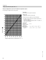
Page 37: ...measurement with the actual temperature displayed for scanning see page 21 Check the installation and replace sensor if necessary in case of severe deviation Specification Protection IP 32 Permiss amb...

Page 38: ...both leads 3 Compare the test result with the actual temperature for scanning see page 21 Check the installation and replace sensor if necessary in case of severe deviation Specification Protection IP...

Page 39: ...ate from the curve values repeat the sensor test and compare with the actual temperature for scanning see page 21 4 Depending on the result replace cable or outdoor temperature sensor 5 Scan actual te...

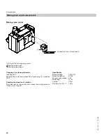
Page 40: ...see page 41 Remove the cover and reinsert the 3 pole plug A turned by 180 Checking the direction of rotation The relay test of the control unit moves the mixing valve to Open and Closed Specification...

Page 41: ...ired see mixing valve installation instructions Note For system with Modular Divicon reverse the rotational direction Factory default setting of the mixing valve motor rotational direction Change the...

Page 42: ...rol C control panel Electro mechanical temperature aquastat according to the liquid expansion principle Switches the heating circuit pump OFF when the set value has been exceeded In such cases the sup...

Page 43: ...changes can be made via coding addresses A0 b0 to b9 C0 to C2 C8 E1 E2 and F2 see overview A Wall mounting base for Vitotrol 200 B To the control unit C Separate room temperature sensor Connection 2...

Page 44: ...key ON 1 2 3 4 Specification Power supply via KM BUS Safety class III Protection IP 30 Permiss ambient temperature in operation 0 to 40 C 32 to 104 F in storage and in transport 20 to 65 C 4 to 149 F...

Page 45: ...Energy saving and party mode Function changes can be made via coding addresses A0 b0 to b9 C0 to C2 C8 E1 and E2 and F8 see overview A Wall mounting base for Vitotrol 300 B To the control unit C Separ...

Page 46: ...ey 1 2 3 4 ON When connecting a separate room temperature sensor set DIP switch S3 3 to ON Specification Power supply via KM BUS Safety class III Protection IP 30 Permiss ambient temperature in operat...

Page 47: ...e diagram above The total length of all KM BUS cables should be limited to 50 m 164 ft Version 2 A To control unit B Junction box on site C Vitotrol 1 D Vitotrol 2 E Vitotrol 3 F Additional BUS users...

Page 48: ...ance at terminals 9 and 13b 3 Compare the measurement with the actual temperature displayed for scanning see page 21 Check the installation and replace sensor if necessary in case of severe deviation...

Page 49: ...ree contact A Main disconnect if required B DIP switch see table DIP switch Function 1 to 3 OFF Controlling the feed pump 1 ON Mixing valve circuit reduced mode M1 2 ON Mixing valve circuit reduced mo...

Page 50: ...No can be selected Coding 1 Calling up coding 1 1 Press 9 and w simultaneously for approx 2 s 2 Select the required coding address with or the address flashes confirm with the value flashes 3 Change t...

Page 51: ...HW heating 00 5 Mixing valve circuit M1 and M2 without DHW heating 00 6 Mixing valve circuit M1 and M2 with DHW heating 00 7 Mixing valve circuit M2 and M3 without DHW heating 00 8 Mixing valve circui...

Page 52: ...3 to A2 15 No function Summer econ M1 M2 M3 A5 5 With heating circuit pump logic function A5 0 Without heating circuit pump logic function Supply min temp M1 M2 M3 C5 20 Electronic minimum supply tem...

Page 53: ...w simultaneously for approx 2 seconds confirm with 2 Select the required coding address with or the address flashes confirm with the value flashes 3 Change the value with or confirm with The display b...

Page 54: ...ing 4b 0 Sensor aJB not installed 4b 1 Sensor aJB installed e g return temperature sensor automatic recognition 4C 0 Connection on plug s M1 Heating circuit pump 4C 1 Primary pump DHW tank storage sys...

Page 55: ...and after external changeover during operation with permanently standard room temperature 64 0 No DHW heating DHW re circulation pump OFF p Enable constant DHW heating and DHW re circulation pump ON...

Page 56: ...ication module automatic recognition 77 10 LON participant number 77 1 to 77 99 LON participant number adjustable from 1 to 99 Note Allocate each number only once 78 1 With LON communication module LO...

Page 57: ...programming unit and the remote control mixing valve circuit M1 8E 2 at the programming unit and remote control unit mixing valve circuit M2 8E 3 at the programming unit and remote control unit mixin...

Page 58: ...it M1 M2 99 4 Mixing valve circuit M3 99 5 Mixing valve circuit M1 M3 99 6 Mixing valve circuit M2 M3 99 7 Mixing valve circuit M1 M2 M3 9A 0 Connection at terminals 1 and 2 in X6 on module A2 9A 1 Co...

Page 59: ...34 F there is a risk of pipes outdoor the thermal insulation of the house freezing up Particularly the standby mode should be taken into consideration e g during holidays A3 9 A3 8 A3 7 A3 6 A3 5 A3...

Page 60: ...lus 1 F This value is based on the adjusted outdoor temperature comprising the actual outdoor temperature and a time constant The time constant takes the cooling down of an average building into accou...

Page 61: ...m temperature hook up b2 8 With remote control unit and for the heating circuit operation with room temperature hook up must be encoded Room influence factor 8 b2 0 Excluding room influence b2 1 to b2...

Page 62: ...art up time optimisation b7 1 With start up time optimisation max offset 2 h 30 min b7 2 With start up time optimisation max offset 15 h 50 min b8 10 With remote control unit and for the heating circu...

Page 63: ...255 Adjustable operating time from 10 to 255 seconds C4 1 Mixing valve algorithm Standard C4 0 C4 2 and C4 3 Controller responds too quickly cycles between Open and Closed Select a lower value Control...

Page 64: ...E2 99 Display correction 0 1 K to Display correction 4 9 K F1 0 Slab curing function inactive F1 1 to F1 4 Slab curing function adjustable in accordance with four optional temperature time profiles s...

Page 65: ...F9 14 If the outdoor temperature is under 14 C 7 F the set reduced room temperature will be raised to the value of the set standard room temperature See example 1 on page 66 F9 10 to F9 60 Temperature...

Page 66: ...art of operation with standard room temperature B Set supply temperature in accordance with the set heating curve C Raised set supply temperature in accordance with coding address FA 50 C 20 60 C 122...

Page 67: ...ime profile 2 F1 2 Temperature time profile 3 F1 3 Temperature time profile 4 F1 4 5581 529 v1 0 08 2006 Flow temperature C 1 5 10 15 20 25 30 Days 50 40 30 20 10 Flow temperature C Days 50 40 30 20 1...

Page 68: ...68 Coding 5581 529 v1 0 08 2006...

Page 69: ...mperature sensor 043 DHW tank temperature sensor with plug 047 LON communication module 048 Electronics PCB mixing valve extension only for model HK3S 049 Main PCB low voltage 050 Electronics PCB 051...

Page 70: ...70 Parts lists Parts list model HK1S and HK3S 5581 529 v1 0 08 2006 005 009 004 013 021 006 007 022 010 1 1 1 2 001 003...

Page 71: ...and boiler rooms standard ambient conditions during storage and transport 20 to 65 C Rated relay output breaking capacity at 120VAC Heating circuit pump s or Primary pump DHW tank storage system 4 2 A...

Page 72: ...mode 31 60 External connections 11 External heating program changeover 11 57 External Mixing valve open 11 58 External Mixing valve closed 11 58 F Fault history 29 Fault manager 14 15 Fault memory 29...

Page 73: ...anning operating conditions 23 Scanning set temperatures 21 Scanning set values 21 Scanning temperatures 21 Sensors checking 16 Service level summary 20 Set DHW temperature 35 Set room temperature adj...

Page 74: ...74 Applicability Applicability Valid for control units Vitotronic 050 model HK1S Part no 7187 105 Vitotronic 050 model HK3S Part no 7187 109 5581 529 v1 0 08 2006...

Page 75: ...75 Notes 5581 529 v1 0 08 2006...

Page 76: ...0590 www viessmann us com mail viessmann us com 76 Quick Reference C F 40 40 35 31 25 13 20 4 18 0 16 3 14 7 12 10 10 14 9 16 8 18 7 19 6 21 5 23 4 25 3 27 2 28 1 30 0 32 1 34 2 36 3 37 4 39 5 41 6 43...

Reviews: