21
+
+
‒
‒
‒
+
‒
+
PE
N
L
0V
24V
A
SYS
RST
RUN
l/0
MS
NS
BT
SD
RESET
STOP
RUN
U6
U5
U4
U3
U2
U1
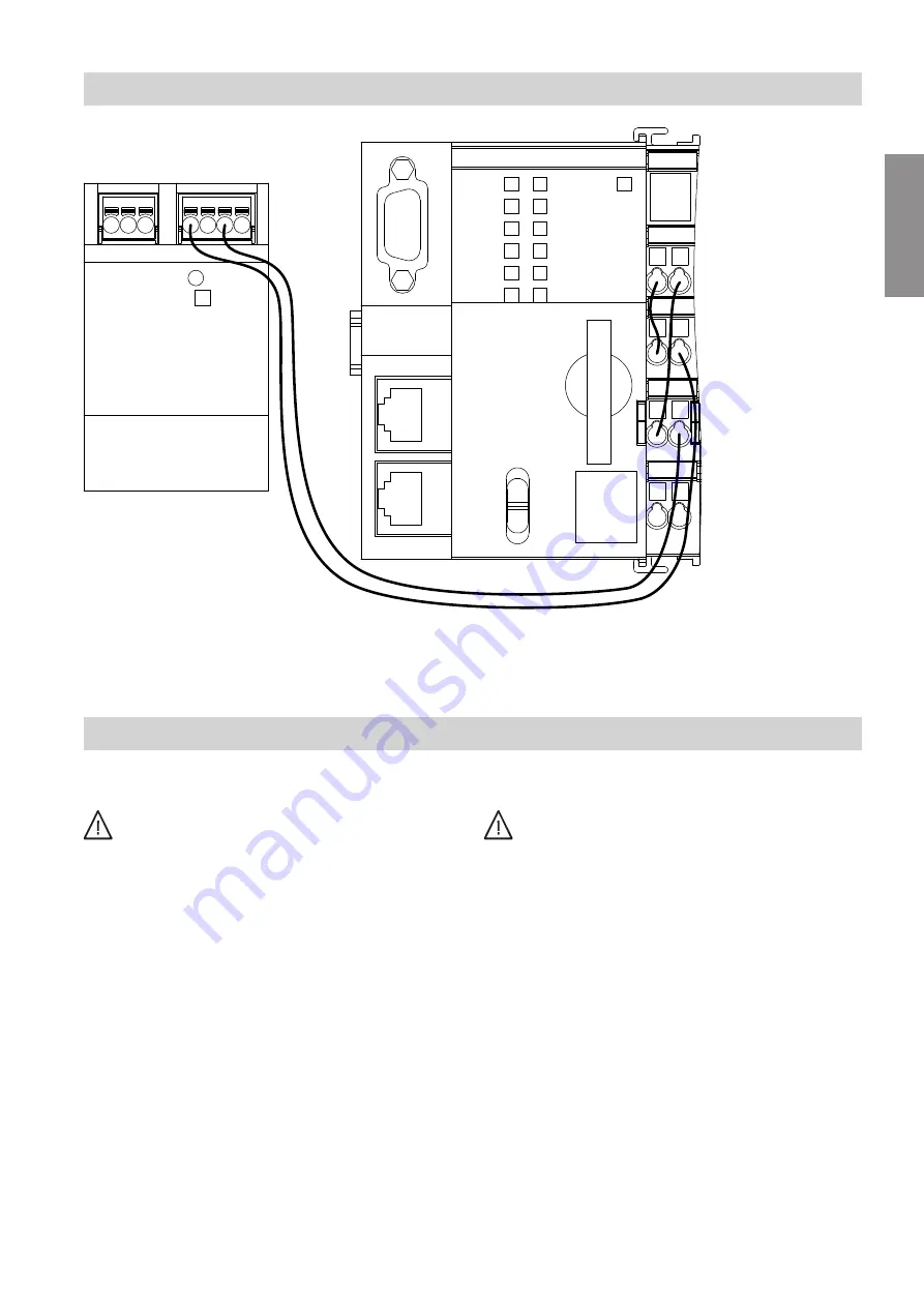
Fig. 13
A
Cable cores between gateway and power supply
unit (standard delivery)
Power supply
General information
Danger
Incorrect wiring can lead to serious injury from
electrical current and result in appliance dam-
age.
■
Route extra low voltage (ELV) leads < 42 V
separately from cables > 42 V/230 V~.
■
Strip as little of the insulation as possible,
directly before the terminals. Bundle cables
close to the corresponding terminals.
■
Secure cables with cable ties.
Danger
Incorrect core assignment can result in serious
injury and damage to the appliance.
Take care not to interchange cores "L1" and "N":
L1 Brown (BN)
N
Blue (BU)
PE Green/yellow (GNYE)
!
Please note
Not grounding or incorrectly grounding the top-
hat rail can lead to damage to the components
and to interference during data transmission.
Ground the top-hat rail as shown in the following
diagram.
The gateway is connected to the public low voltage
network via the power supply unit (standard delivery).
Mains type TN-S/TT: Separate neutral and protective
conductors in the entire system.
The mains voltage should be single-phase, 100 to
240 V, 50/60 Hz and must be within the voltage range
limits defined in the VDE regulations.
Installation sequence
Connecting the gateway to the power supply unit
(cont.)
6175460
Installation


