Overview
14
ViewCast
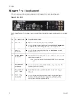
Niagara Pro II back panel
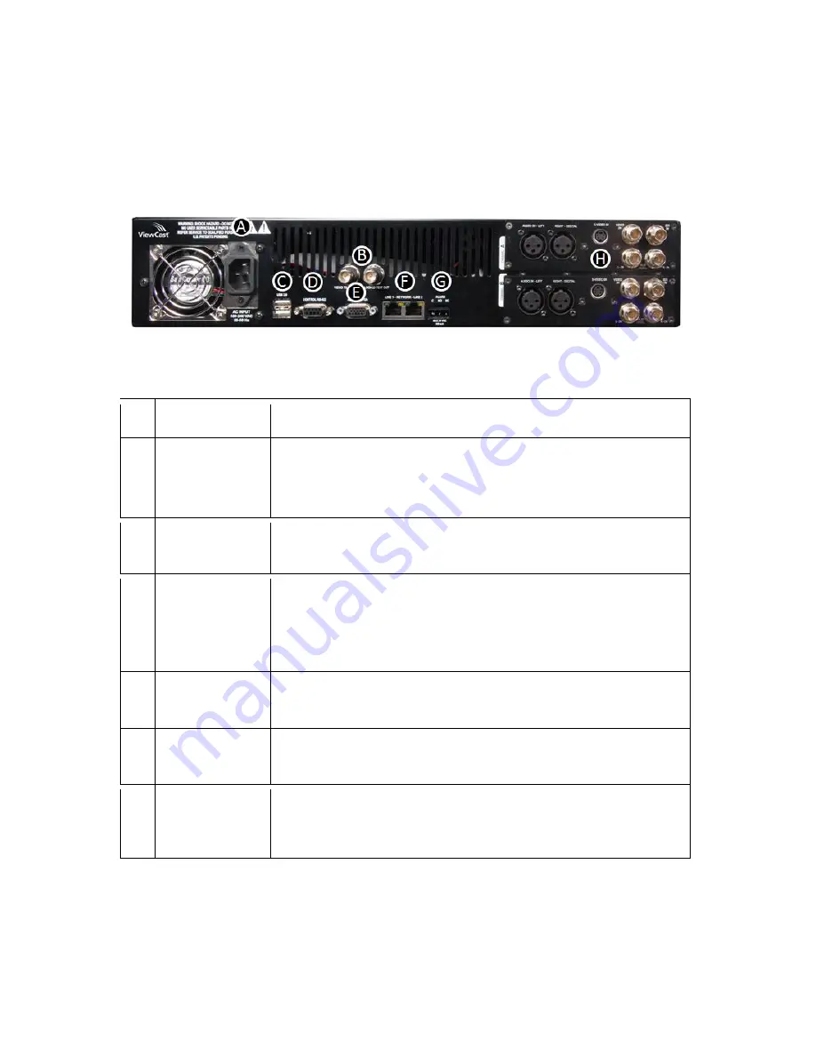
The connectors and other components are on the Niagara Pro II back panel (Figure 3).
Figure 3. Back Panel
Using the reference chart below, you can connect the appropriate device and power to the Niagara
Pro II.
A
AC Power input
Provides system power.
B
Video Test
BNC connector for composite video IN/OUT.
Use to connect a video test signal, such as a color bar generator,
to calibrate the video settings for video capture sessions.
C
USB 2.0
Connectors
Use to connect USB storage devices, or USB devices such as,
keyboard and mouse.
D
Control RS-422
Connector
Standard RS-422 port (9-pin D connector) that you can use with
deck control software.
Note: ViewCast does not currently provide software for this
port.
E
Auxiliary VGA
Connector
Use to connect an external VGA monitor, so you can view the
operating system interface.
F
Network Ports
(line 1 and 2)
Dual Ethernet ports provide redundant connections to your
network.
G
Alarm Relay
Connector
Use to connect an external device (such as an audible bell or
buzzer) so if the system fails it triggers an external audible
sound. (Not currently implemented)
Summary of Contents for Niagara Pro II
Page 1: ......
Page 26: ......
Page 62: ...Advanced Operations 56 ViewCast...
Page 144: ......
Page 163: ...Niagara Pro II User Guide ViewCast 157 Access health menu CPU status Memory available...
Page 165: ...Niagara Pro II User Guide ViewCast 159 View network settings Enable DHCP...
Page 166: ...Appendix D System Menu LCD Display 160 ViewCast Set static IP addresses...
Page 167: ...Niagara Pro II User Guide ViewCast 161 Set gateway address...
Page 168: ...Appendix D System Menu LCD Display 162 ViewCast Set date and time Set video standard x3...


