background image

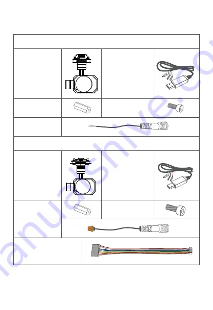
1.2 In the Box

2.

A. Standard Version

B. Viewport Version

Gimbal Camera

x 1 pc

USB to TTL Cable  

x 1 pc

Power Cable

x 1 pc

Gimbal Camera

x 1 pc

USB to TTL Cable  

x 1 pc

M3 Screw

x 8 pcs

Copper Cylinder

x 4 pcs

Copper Cylinder

x 4 pcs

Power Cable

x 1 pc

PWM Control Cable

x 1 pc

M3 Screw

x 8 pcs

2.

Summary of Contents for Z5S

Page 1: ...User Manual Z5S SONY a5100 Gimbal Camera Standard Version 标准版 快拆版 Viewport Version For more details please scan the QR code or visit our website www viewprotech com ...

Page 2: ... APS C sensor with a5100 interchange able lens Z5S is widely used in UAV industries of electrical industry transmission towers electric substations zoom aerial photography and other industrial applications Congratulations on purchasing your new Viewpro product Please read this entire document carefully Failure to read or follow instruc tions and warnings in this document may result in damage to yo...

Page 3: ...t Version Gimbal Camera x 1 pc USB to TTL Cable x 1 pc Power Cable x 1 pc Gimbal Camera x 1 pc USB to TTL Cable x 1 pc M3 Screw x 8 pcs Copper Cylinder x 4 pcs Copper Cylinder x 4 pcs Power Cable x 1 pc PWM Control Cable x 1 pc M3 Screw x 8 pcs 2 ...

Page 4: ...view TTL S BUS Control Cable x 1 pc TTL Connect Cable x 3 pcs Ethernet Cable x 1 pc 3 Viewport Control Box Back Side Standard Version Viewport Version 11 11 12 10 10 2 Installation Instruction 3 2 4 1 9 7 6 5 8 ...

Page 5: ...face 12 Viewport unlock button 5 Damping ball PITCH Yellow Jumper Cap TX RX GND YAW MODE ZOOM FOCUS PIC REC MULTI USB AV 5V output GND 1 2 3 The input voltage cannot be higher than 6S The pin insertion interface cannot be connected with power supply The yellow jumper cap cannot be removed Please ensure that there isn t any obstacle while the motor rotating Please remove the obstacle immediately if...

Page 6: ...ontrol Box Printing Viewport Version 5 Left Side Right Side PITCH YAW MODE ZOOM FOCUS PPM PIC REC MULTI 5V GND CVBS 3S 6S GND POWER PWM GND CANL CANH DC5V GND 5V S BUS TTX GND RXD TXD RX RX TX TX ETHERNET UART S BUS CAN ...

Page 7: ...Unit mm 2 3 Device Dimensions Standard Version 6 60 124 6 4 φ3 1 24 5 126 6 152 1 33 ...

Page 8: ...Unit mm 7 2 3 Device Dimensions Viewport Version Control Box 124 6 126 6 157 8 78 4 φ3 1 78 ...

Page 9: ... with the direction specified by the UAV 2 Fix one end of the copper cylinder on the screw hole of lower damping board and use M3 screw to fasten it 3 According to the provided screw hole dimension you can make suitable mounting holes on the UAV mounting board and fixes the other end of the copper cylinder on the mounting board of the UAV Viewport version is the same Front ...

Page 10: ...elease Instruction 9 1 Make sure the two white stripes indicated in above picture are aligned with each other If the stripes are not aligned to each other please pinch the connector part and turn it to left manually ...

Page 11: ...e gimbal camera anticlockwise 3 When you hear click sound when red dot is aligned to the red triangle means the gimbal camera and Viewport has been locked 4 To unlock the Viewport you need to press on unlock button and rotate the gimbal camera clockwise till the white dot align to the red triangle Then pull the gimbal out from the Viewport ...

Page 12: ...s Optional Network Ethernet output interface support RTSP UDP video streaming 720P 1080P 25 30 fps Default RTSP output IP address RTSP 192 168 1 100 stream0 output resolution 1080P frame rate 25fps bit rate 2M Optional Above output mode is optional HDMI and IP output cannot coexist at the same time Please subject to your actual product Make sure device is power off when inserting the TF card hot p...

Page 13: ...uce the required number of PWM channels 3 1 1 PWM Connection Diagram Connect pitch chan nel as example 3 Signal Control When using user interface software Viewlink for network connection the network of external device computer should be the IP address 192 168 1 2 choose the last byte among 2 254 can not be 100 same as the gimbal subnet mask 255 255 255 0 Default gateway 192 168 2 1 and all firewal...

Page 14: ...13 Remote Controller Remote Controller Connection Diagram Standard Version Connection Diagram Viewport Version Receiver MULTI PIC REC FOCUS ZOOM MODE YAW PITCH PWM IN GND 5V OUTPUT Receiver ...

Page 15: ... knob or 3 gear switch on remote control are optional 3 gear switch as example 3 Mode PWM Mode channel in to adjust speed control one key to Home position etc functions Rotary knob or 3 gear switch on remote control are optional 3 gear switch as example Low Gear Pitch Up Position 1 Middle Gear Pitch Stop Position 2 High Gear Pitch Down Position 3 Low Gear Yaw Left Position 1 Middle Gear Yaw Stop P...

Page 16: ...aw not follows by frame 3 4 Operate 4 times continuously and quickly from position 2 3 2 3 2 3 2 3 2 to enable Follow Yaw Mode gimbal yaw follows by frame Position 1 Low speed mode control pitch yaw with this mode at lowest speed Position 2 Middle speed mode control pitch yaw with this mode at middle speed Position 3 High speed mode control pitch yaw with this mode at highest speed If it is contro...

Page 17: ...Pic Rec channel in to control take picture and record Joystick rotary knob or 3 gear switch on remote control are optional 3 gear switch as example Switch from Position 2 to 1 manual focus Switch from Position 2 to 3 manual focus Low Gear Zoom Out Position 1 Middle Gear Stop Zoom Position 2 High Gear Zoom In Position 3 Low Gear PIP switch Position 1 Middle Gear No control Position 2 High Gear IR c...

Page 18: ...ttings can only be saved after off camera Switch from Position 2 to 3 Start record repeat operation to stop record 7 Multi On off camera rotary knob or 3 gear switch on remote control are optional 3 gear switch as example TTL communication requirements TTL signal is 3 3V baud rate 115200 data bit 8 stop bit 1 no parity HEX send and receive Low Gear Position 1 Middle Gear Position 2 High Gear Posit...

Page 19: ... TX GND S BUS TTX RXD GND TXD RX RX TX TX GND GANL CANH DC5V RX White TX RX GND TX Green GND Black Control Box Viewport Control Box USB to TTL Cable USB to TTL Cable Connection Diagram Standard Version Connection Diagram Viewport Version ...

Page 20: ...us signal GND connect to the GND interface of the control box Wiring Diagram Take Futaba remote control for example Install Viewlink control software to test the functions directly Users may choose to develop their own software please contact technical support for TTL control protocol file ViewLink is a user interface developed by Viewpro for Viewpro gimbal cameras you can download it from Viewpro...

Page 21: ...GND 5V S BUS TTX RXD GND TXD 20 S BUS 5V OUTPUT GND Remote Control Remote Control Receiver Receiver Wiring Diagram Standard Version Wiring Diagram Viewport Version ...

Page 22: ...ions the function of channel is consistent with corresponding channel in PWM function description TTL control and S bus control cannot coexist at the same time for standard version The default control is TTL if no requirement The user can set to S bus control if needed please contact with our technical support for the setting instruction User can set the channels by setting serial command accordin...

Page 23: ...put Local storage Vibration angle Pitch Roll 0 02 Yaw 0 02 One key to center Control method PWM TTL S BUS 0 40 micro HDMI HD output 1080P 50fps IP Angle range of structure design Pitch Tilt 120 Roll 40 Yaw Pan 300 360 N IP output version Pitch Tilt 45 90 Yaw Pan 290 360 N IP output version Angle range of software design SD card Up to 128G class 10 FAT32 or ex FAT format 4 Specification ...

Page 24: ...cording format AVCHD MP4 XAVC S White balance Auto Focus type Fast Hybrid AF phase detection AF contrast detection AF Image format RAW RAW J FINE STD Backlight compensation Yes Image size pixels 3 2 23 L 6000 x 4000 24 M M 4240 x 2832 12 M S 3008 x 2000 6 0 M Shutter speed second Movies 1 4000 to 1 4 1 3 steps 1 50 in AUTO mode up to 1 25 in Auto slow shutter mode Still images 1 4000 to 30 sec Bul...

Page 25: ...change configuration parameters of Z5S IP output version A Login in default IP address with IE browser enter audio and video configuration video management to modify image size encoding frame rate encoding bit rate Enter the Network protocol configuration TCP IP IP address gateway to modify the IP address 5 FAQ 1pc gimbal camera device Hight quality plastic box with foam cushion AF mode AF A Autom...

Reviews: