Step
Figure
Description
21
1.
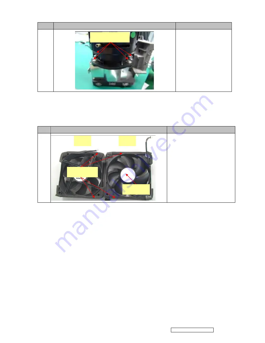
Loosen the four screws on
the Lens.
2. Remove the Lens carefully.
3.3
Assembly FAN Module
Step
Figure
Description
1
Assemble Fan1(J2394-0143-01) and
Fan2 (J2394-0144-00 ):
1. Paste the Fan Pad (P4E38-1070-00)
on the middle of it.
2. Paste the Fan Sponge*4
(P4G38-1180-00) on the top and
bottom of it as picture shown.
P0335-7010-01*4
Fan Pad
Fan1
Fan2
Fan Sponge*4
Confidential - Do Not Copy
ViewSonic Corporation
Pro8400
23
Summary of Contents for Pro8400 Series VS13647
Page 10: ...D Remote Control Confidential Do Not Copy ViewSonic Corporation Pro8400 7 ...
Page 11: ...Confidential Do Not Copy ViewSonic Corporation Pro8400 8 ...
Page 15: ...1 4 Pro8400 System Block Diagram Confidential Do Not Copy ViewSonic Corporation Pro8400 12 ...
Page 51: ...7 2 Packing drawing Confidential Do Not Copy ViewSonic Corporation Pro8400 48 ...
Page 52: ...Confidential Do Not Copy ViewSonic Corporation Pro8400 49 ...
Page 56: ...Confidential Do Not Copy ViewSonic Corporation Pro8400 53 ...
Page 57: ...Appendix B IR Control Code Confidential Do Not Copy ViewSonic Corporation Pro8400 54 ...


