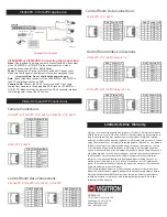
Control Room Data Connections:
Video +
Video
Data +
Power
Power +
Data
Power +
Power
Camera Connections:
Vi1053VPD, Vi1508VPD, Vi1516VPD, Vi1408VPD, Vi1416VPD
Video/Power/Data
Local Power
Vi1516VPD
16-Ch VPD Powered Combiner Receiver
Cat-5
Cat-5
Cat-5
1053VPD
Power
Power
Data
110/220 VAC
16 Coax Jumpers
Data
DVR
1053VPD
Application Diagram
Vi508VPD - Vi1516VPD Application
Video, Data and UTP Connections
Limited Lifetime Warranty
Pin#
1
2
3
4
5
6
7
8
1
2
3
4
5
6
7
8
Pin#
Data-1 +
Data-1 -
Data-2 +
Data-3 -
Data-3 +
Data-2 -
Data-4 +
Data-4 -
Camera 1-4
Vi1508VPD or Vi1516VPD: Connecting the Control End
Video:
Use provided Coax jump cables to connect the BNC video output
of the Vi1508VPD or Vi1516VPD to the video input of your video
receiving unit such as a DVR or Matrix Switch.
Power:
Connect the AC power cord to the unit and AC power outlet.
Make sure that the power requirement is in the recommended range.
Important Note: Do not overload the power supply.
Data:
Connect the Data connector of the Vi1508VPD or Vi1516VPD to
the PTZ controlling unit such as DVR.
Camera Cable:
Connect the RJ-45 connector of each Cat-5 cable
coming from cameras to the appropriate RJ-45 jack on Vi1508VPD or
Vi1516VPD. Make sure that the pin-out of the RJ-45 connector matches
the following color code of the Cat-5 wires
Pin#
Data-5 +
Data-5 -
Data-6 +
Data-7 -
Data-7 +
Data-6 -
Data-8 +
Data-8 -
Camera 5-8
1
2
3
4
5
6
7
8
Pin#
Data-9 +
Data-9 -
Data-10 +
Data-11 -
Data-11 +
Data-10 -
Data-12 +
Data-12 -
Camera 9-12
Pin#
Data-13 +
Data-13 -
Data-14 +
Data-15 -
Data-15 +
Data-14 -
Data-16 +
Data-16 -
Camera 13-16
Vi1516VPD, Vi1416VPD
Vi1408VPD, Vi1416VPD, Vi1508VPD, Vi1516VPD
1
2
3
4
5
6
7
8
1
2
3
4
5
6
7
8
Control Room Video Connections:
1
2
3
4
5
6
7
8
Pin#
Video-1 +
Video-1 -
Video-2 +
Video-3 -
Video-3 +
Video-2 -
Video-4 +
Video-4 -
Camera 1-4
Pin#
Video-5 +
Video-5 -
Video-6 +
Video-7 -
Video-7 +
Video-6 -
Video-8 +
Video-8 -
Camera 5-8
1
2
3
4
5
6
7
8
Pin#
Video-9 +
Video-9 -
Video-10 +
Video-11 -
Video-11 +
Video-10 -
Video-12 +
Video-12 -
Camera 9-12
Pin#
Video-13 +
Video-13 -
Video-14 +
Video-15 -
Video-15 +
Video-14 -
Video-16 +
Video-16 -
Camera 13-16
Vi1516VPD, Vi1416VPD (Camera 9-16)
Vi1408VPD, Vi1416VPD (Camera 1-8)
1
2
3
4
5
6
7
8
1
2
3
4
5
6
7
8
Vigitron, Inc. warrants that all Vigitron products (“Product”), if used in accordance
with these instructions, will be free of defects in material and workmanship for as
long as the original end user purchaser owns the product. At Vigitron's option,
defective product will be repaired, replaced or substituted with a product of equal
value. This warranty does not apply if, in the judgment of Vigitron, Inc., the Product
fails due to damage from shipment, handling, storage, accident, abuse or misuse,
or if it has been used or maintained not conforming to Product manual instruc-
tions, has been modified, or serial number removed or defaced. Repair by anyone
other than Vigitron, Inc. or an approved agent will void this warranty Vigitron, Inc.
shall not under any circumstances be liable to any person for any incidental,
indirect or consequential damages, including damages resulting from use or
malfunction of the product, loss of profits or revenues or costs of replacement
goods. The maximum liability of igitron, Inc. under this warranty is limited to the
original purchase price of the Product.
Prior to returning any defective Product, the end customer or the reseller from
whom the end customer originally purchased the Product must obtain a Return
Materials Authorization (RMA) number from igitron, Inc. All defective Products
should be returned to igitron, Inc. with shipping charges prepaid. No collect
shipments will be accepted.
VIGITRON, INC.
7810 Trade Street, Suite 100
San Diego, CA 92121, U.S.A.
Phone: (858) 484-5209
Fax: (858) 484-1205
Video +
Video
No Connect
Power
Power +
Power +
Power
Vi1051VP, Vi1054VP
Video/Power/Data
Pin#
1
2
3
4
5
6
7
8
No Connect
Control Room Data Connections:
Vi1051VP
Vi1054VP


