background image

Viglen BX110 Chassis Quick Start Guide


13

4.

  Place the carrier into the chassis and push the lever to securely lock the carrier in 

place.


Installing 5¼ Inch Devices 


Before proceeding, be sure you are thoroughly familiar with the information in “Before 
You Begin” at the front of this chapter.   
 
Installing 5¼ inch devices in the chassis is a two fold step: 
 

1.

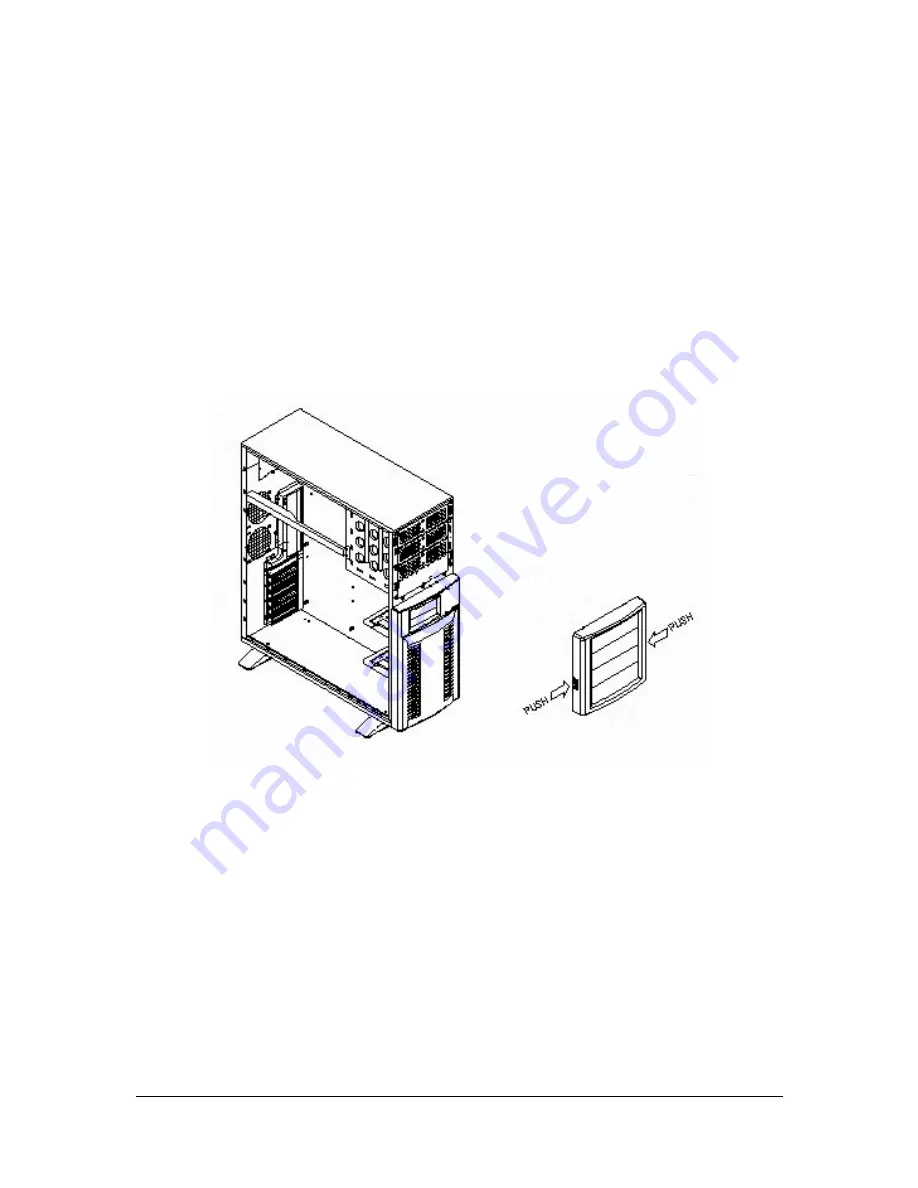
  The top part of the front panel needs to be removed; this is done by pressing two 

buttons on either side of the front panel as shown overleaf.


Figure 5: Removal of the top front panel for access to the 5¼ inch bays 


2.  Secondly each device to go in the bays must be secured to plastic slide rails 

supplied with the system, this allows peripherals to be removed quickly from the 
system should the need arise and is also part of the chassis tool-less design. The 
slide rails are attached to devices as shown below. 

Summary of Contents for BX110

Page 1: ... C O M P U T E R S N E T W O R K S S O L U T I O N S M i n d s T h i n k G r e a t Viglen BX110 Chassis Product Guide ...

Page 2: ... Environment laboratory To gain a CE mark the Viglen computer range has had to undergo many difficult tests to ensure it is Electromagnetically Compatible These are carried out in the in house Environment lab at Viglen Headquarters We have made every effort to guarantee that each computer leaving our factory complies fully to the correct standards To ensure the computer system maintains compliance...

Page 3: ...kup Copyright 2001 Viglen Limited All Rights Reserved Viglen BX110 Chassis Product Guide Version 1 0 Printed in the United Kingdom Liability No warranty or representation either expressed or implied is made with respect to this documentation its quality performance merchantability or fitness for a particular purpose As a result the documentation is licensed as is and you the licensee are assuming ...

Page 4: ...sure that the total ampere rating of the equipment plugged into extension cord does not exceed the extension cord ampere rating Also make sure that the total rating of all products plugged into the wall outlet does not exceed the fuse rating 9 Never push objects of any kind into this product through cabinet slots as they may touch dangerous voltage points or short out parts that could result in a ...

Page 5: ...uttons 7 Chapter 3 Removing and installing components 8 Before you begin 8 Warnings 8 Tools and supplies needed 9 Gaining access to the system motherboard 9 Removing the cover 9 Replacing the cover 10 Removing the Hard Disk Drive s 11 Installing the Hard Disk Drive s 12 Installing 5 device s 13 Replacing the Chassis fan s 14 Contacting Viglen 16 Notes 17 ...

Page 6: ...etal chassis minimises EMI and radio frequency interference RFI The removable access cover is attached to the chassis with two screws can be secured with locking handle and provides easy access to the S845WD1 E Motherboard and power supply Figure 1 Overview of BX110 Chassis Components ...

Page 7: ...Viglen BX110 Chassis Quick Start Guide 6 Chapter 2 Controls connectors and Indicators Front panel Figure 2 Overview of BX110 Front Panel ...

Page 8: ...em Control Panel LEDs The control panel provides system activity information LEDs indicate power on and hard disk drive activity The control panel also includes a main power button and a system reset button HDD On the BX110 System this light indicates IDE Hard drive activity when flashing Chassis Back Panel The input output connectors are accessible at the back panel of the chassis NOTE The mouse ...

Page 9: ...how you can ensure that your system meets safety and regulatory requirements WARNINGS This chapter is intended for qualified technical personnel with experience installing and configuring systems SYSTEM POWER ON OFF The Power button on the system front panel DOES NOT remove AC power to the system Some circuitry in the system may continue to operate even though the front panel Power button is off A...

Page 10: ...on is available you can reduce the risk of electrostatic discharge ESD damage by doing the following Wear an antistatic wrist strap and attach it to a metal part of the system Touch the metal on the system chassis before touching the system components Keep part of your body in contact with the metal system chassis to dissipate the static charge while handling the components Hold the system compone...

Page 11: ...de panel on the system Before proceeding be sure you are thoroughly familiar with the information in Before You Begin at the front of this chapter 1 Position the side cover on the open end of the chassis with the edge closest to the handle facing the back panel of the system 2 Grasp the back edge of the cover and simultaneously push from the back edge until the front edge of the cover meets the sy...

Page 12: ...emove a Hard Drive follow these steps 1 The hard disk Carrier must be removed to allow access to the hard drive 2 Disconnect any cables which are attached to the hard disk such as power and data cables 3 The hard disk carrier is removed by pushing the lever located just above the carrier 4 Slide out the hard drive carrier 5 Using a Phillips screwdriver remove the four screws that attach the drive ...

Page 13: ...k carriers of the system in order to function this is achieved in the following way NOTE This procedure assumes that the hard drives have been removed from the carrier as described in the previous Removing the Hard Drives procedure 1 Place the hard drive within the carrier 2 Align and place the hard drive within the carrier in an empty slot with the SCSI or IDE connector facing away from the chass...

Page 14: ...s is a two fold step 1 The top part of the front panel needs to be removed this is done by pressing two buttons on either side of the front panel as shown overleaf Figure 5 Removal of the top front panel for access to the 5 inch bays 2 Secondly each device to go in the bays must be secured to plastic slide rails supplied with the system this allows peripherals to be removed quickly from the system...

Page 15: ... panel onto the chassis once all devices have been installed Replacing the Chassis Fans In the unlikely event that the chassis fans fail it is imperative that they are replaced as soon as possible to keep the system cool and at operational efficiency Before proceeding be sure you are thoroughly familiar with the information in Before You Begin at the front of this chapter Each of the chassis fans ...

Page 16: ...cing chassis fans please ensure that the fan located in the hard drive caddy will blow air over the hard drives while the one located at the rear of the chassis below the Power Supply sucks air out of the system and blows it out the rear This is essential to maintain an optimum operating environment in the system ...

Page 17: ...rvice Centre Tel 020 8991 3582 Fax 020 8758 7085 E mail service viglen co uk Account Sales Call the department appropriate to your business sector Education Tel 020 8758 7170 Fax 020 8566 7105 E mail education viglen co uk Schools Tel 020 8758 7027 Fax 020 8758 7417 E mail schools viglen co uk Corporate Tel 020 8758 7172 Fax 020 8566 8930 E mail corporate viglen co uk Public Sector Tel 020 8758 70...

Page 18: ...Viglen BX110 Chassis Quick Start Guide 17 Notes ...

Page 19: ...Viglen BX110 Chassis Quick Start Guide 18 ...

Reviews: