VIGOR ELECTRIC CORP.
VB-4DA
4-Channel Analog Outputs Module
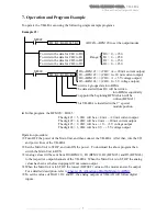
Example #2:
M9000
FROM K1 K30 D10 K1 From the BFM #30 to read the model code
CMP K106 D10 M0
M1 will be turned ON when the code = K106
MOV K250 D0
(K250)→D0
MOV K125 D1
(K125)→D1
MOV K250 D2
(K250)→D2
MOV K125 D3
(K125)→D3
M1
TOP K1 K0 H5500 K1
(H5500)→BFM #0 :
CH1 & CH2 = 0~+10 V voltage output
CH3 & CH4 = +4~+20 mA current output
TO K1 K1 D0 K4
D0 (K250)→BFM #1→CH1 output
D1 (K125)→BFM #2→CH2 output
D2 (K250)→BFM #3→CH3 output
D3 (K125)→BFM #4→CH4 output
●
To execute the program above, on the VB-4DA terminals will be:
Between VOUT1 and COM1 has 10 V output.
Between VOUT2 and COM2 has 5 V output.
Between IOUT3 and COM3 has 20 mA output.
Between IOUT4 and COM4 has 12 mA output.
Check whether the output wiring and/or expansion cables are properly connected on VB-4DA
analog output module. (Refer to the
Chapter #4: Wiring
)
Check that the VB system configuration rules have not been broken, i.e. the number of modules
does not exceed 8.
Ensure that the correct output mode has been selected for the application.
Check that there is no power overload on either the 5 V or 24 V
<< Power Requirement >>
,
remember the loading on the VB Main Unit or a powered extension unit varies according to the
number of extension units or special function units connected.
Put the Main Unit into RUN.
After turning ON or OFF the 24 V DC power for analog signals, the analog output may
fluctuate for approximately 1 second. This is due to time delays in the power supply from the
Main Unit or differences in start time. For this reason, be sure to take preventive measures so
that this output fluctuation will not affect the external units.
VIGOR ELECTRIC CORP.
Tel: 886-2-2620-4393 Fax: 886-2-2620-4976
http://www.vigorplc.com
----------------------------------------------------------------
8
----------------------------------------------------------------
Cautions Regarding Operation


