Wiring
2
IMPORTANT:
Electronic devices are susceptible to lightning and power station electrical surges from both the AC
outlet and the telephone line. It is recommended that a surge protector be installed to protect against such surges.
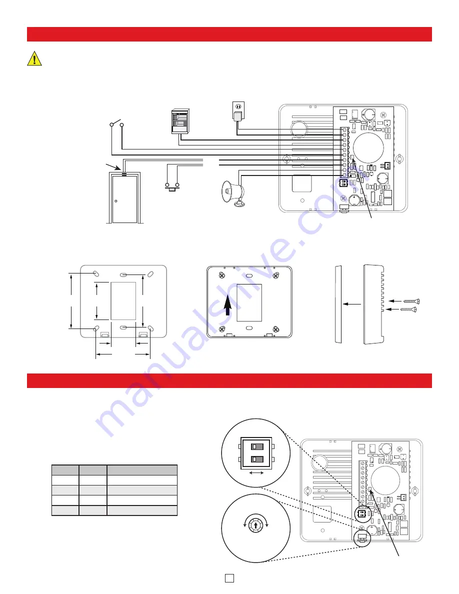
Rear View of the SRL-1
120V AC
PABX/KSU
Common Audible
Contact Closure
Ringing Analog
PABX/KSU Station
- OR -
Magnet
OR
Doorbell or
"Push for
Assistance"
Button
LINE
Test Button
12 VDC
CONTACT
CHIME
EXT SPEAKER
12V DC
Power
Input
Optional 8-Ohm Speaker
(model 25AE shown, not included)
Normally Open
Door Sensor
Switch
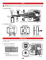
B. Mounting the SRL-1
UP
3.40”
3.30”
2.35”
3.40”
1.55”
Mount the back panel to a wall, a
single gang box or a 4” x 4” junction
box with the arrow pointing up.
Attach the cover to the base with
the two included screws as shown.
Internal View of the
back panel SRL-1
Side View of the SRL-1
Rear View of the SRL-1
Programming
A. Single Line Loud Ringer
The
SRL-1
contains two different functions: single line loud ringer or door chime. Use the following sections to program and
set-up each function.
A. Wiring the SRL-1
1
2
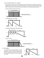
ON
OFF ON
DIP Switches
(bottom view)
Volume
Control
Minimum Maximum
Use a small screw
driver to adjust.
Test Button
Internal View of the SRL-1
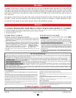
1. DIP Switch Programming
Sw 1
Sw 2
Description
OFF
OFF
Electronic Warble
OFF
ON
Double Gong
ON
OFF
Quadruple Chime
ON
ON
Electronic Bell
2. Test Button
The
Test Button
is used to test the
selected tone and set the volume level.


