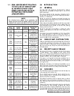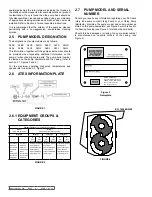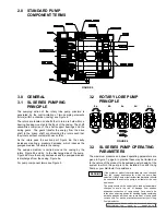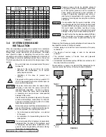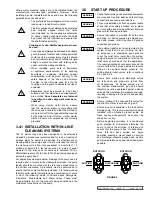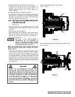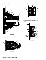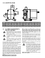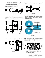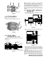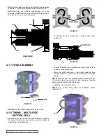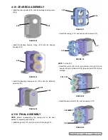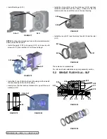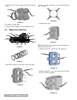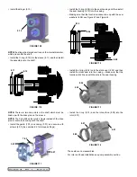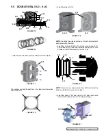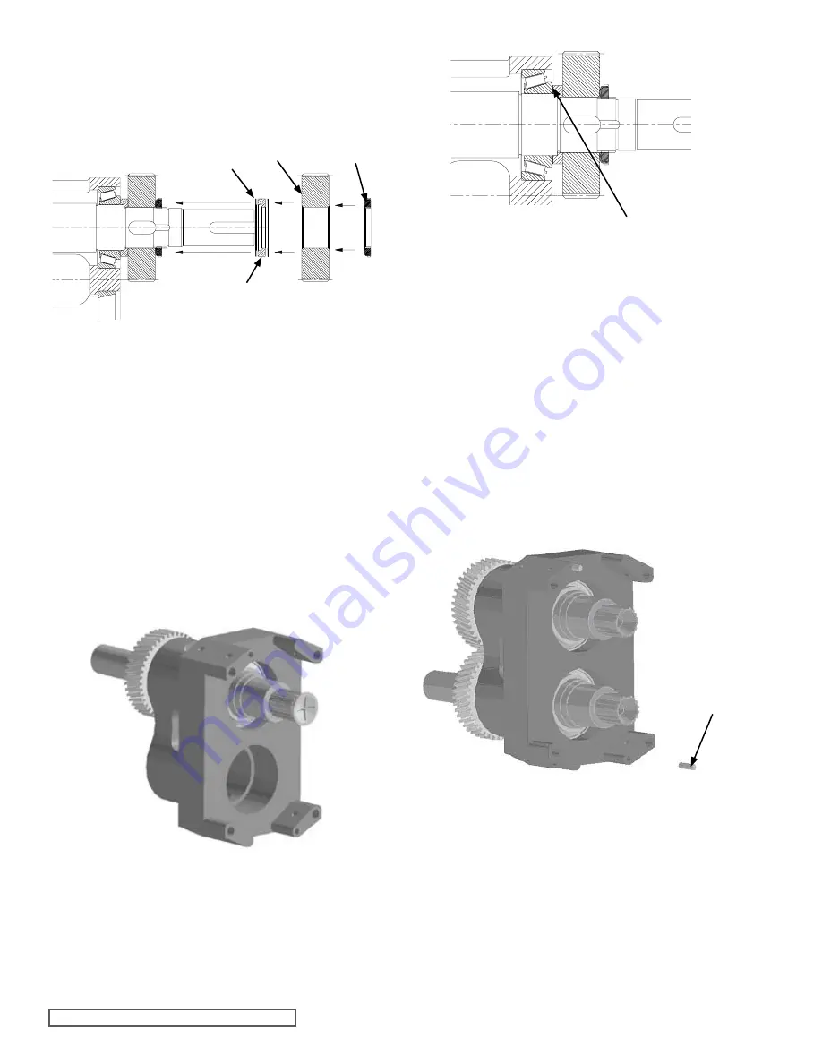
fIGURE 25
To increase the pre-load add shims to position A.
To decrease the pre-load remove Shims from position A.
See section 6.2 for pre-load settings.
POsITION a
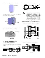
fIGURE 26
4.06
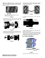
fIGURE 24
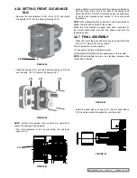
fIGURE 23
5.13
5.06
5.09
5.05
SECTION TSM 288
ISSUE
A
PAGE 14 OF 36
• Install the casing (3.01) onto the bearing housing (4.01) and
use the bolts (4.07) to secure the casing (3.01)
NOTE:
Without the gearbox cover spacers may be required to
ensure the casing is fully clamped in position
NOTE:
The pre-load must be set one shaft at a time.
When the pre-load is set remove the gear and install the gear
keys (5.07)
This procedure must be repeated for the second shaft
4.1.3 CasING assEMblY
• Install the dowels (4.06) into the bearing housing
(See Figure 26)
4.1.2 ROllING TORQUE /
PRE-lOad
Use a torque meter to check the rolling torque see section 6.2
for torque settings.
If the rolling torque is under / over the required amount add /
remove shims to adjust the pre-load to suit (See section 6.2
Fasteners & Torque Settings).
NOTE:
Rolling torque can only be set on new bearings, with no
sealing devices installed i.e. lip-seals or O-rings.
When checking the rolling torque is it important to make sure
the shaft is rotating freely, completely rotate the shaft 10 times
before checking the rolling torque.
The pre-load is set by adding or removing shims in position A
(See Figure 25).
Install 0.25 mm (0.009”) of shims (5.13) , pre-load spacer
(5.05), gear (5.06) and locknut (5.09)
NOTE:
Do not install the gear key or tab washer at this time
When setting the pre-load on the shafts note the pre-load has to
be set on individual shafts, so only install one gear at a time.


