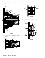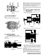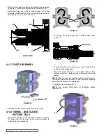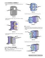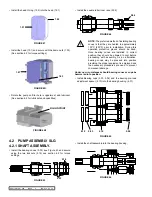
fIGURE 84
fIGURE 82
8.01
8.02
2.01
fIGURE 83
8.01
8.02
8.04
8.06
8.08
8.09
8.17
8.18
8.19
8.20
8.16
8.05
8.03
fIGURE 81
8.04
8.03
fIGURE 78
3.01
7.03
4.07
fIGURE 77
sla-f
slG
5.15
fIGURE 80
fIGURE 79
8.06 / 8.07
8.06
SECTION TSM 288
ISSUE
A
PAGE 24 OF 36
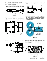
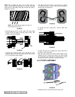
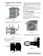
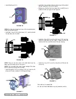
• Install the l-cup (8.01) and the rotary face (8.02) into the rotor
(2.01)
The seals are now assembled.
For rotor and head installation see pump assembly section
5.2 sINGlE flUsH sla – slf
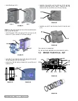
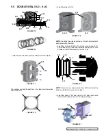
• Install the O-ring (8.04) onto the static seal (8.03) and then
install the static seal into the casing – make sure that the
location slots line up with the pins in the seal housing
• Install the slinger (5.15)
NOTE:
the slinger has raised sections on the internal diameter,
which press onto the shaft
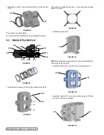
• Install the guard (7.03) and casing (3.01) and secure with
screws (4.07) (See section 6.2 for torque settings)
• Install the O-ring (8.06) into the seal housing and then install
the seal housing (8.07) into the casing
• making sure that the location recesses line up with the seal
washers (8.07)

