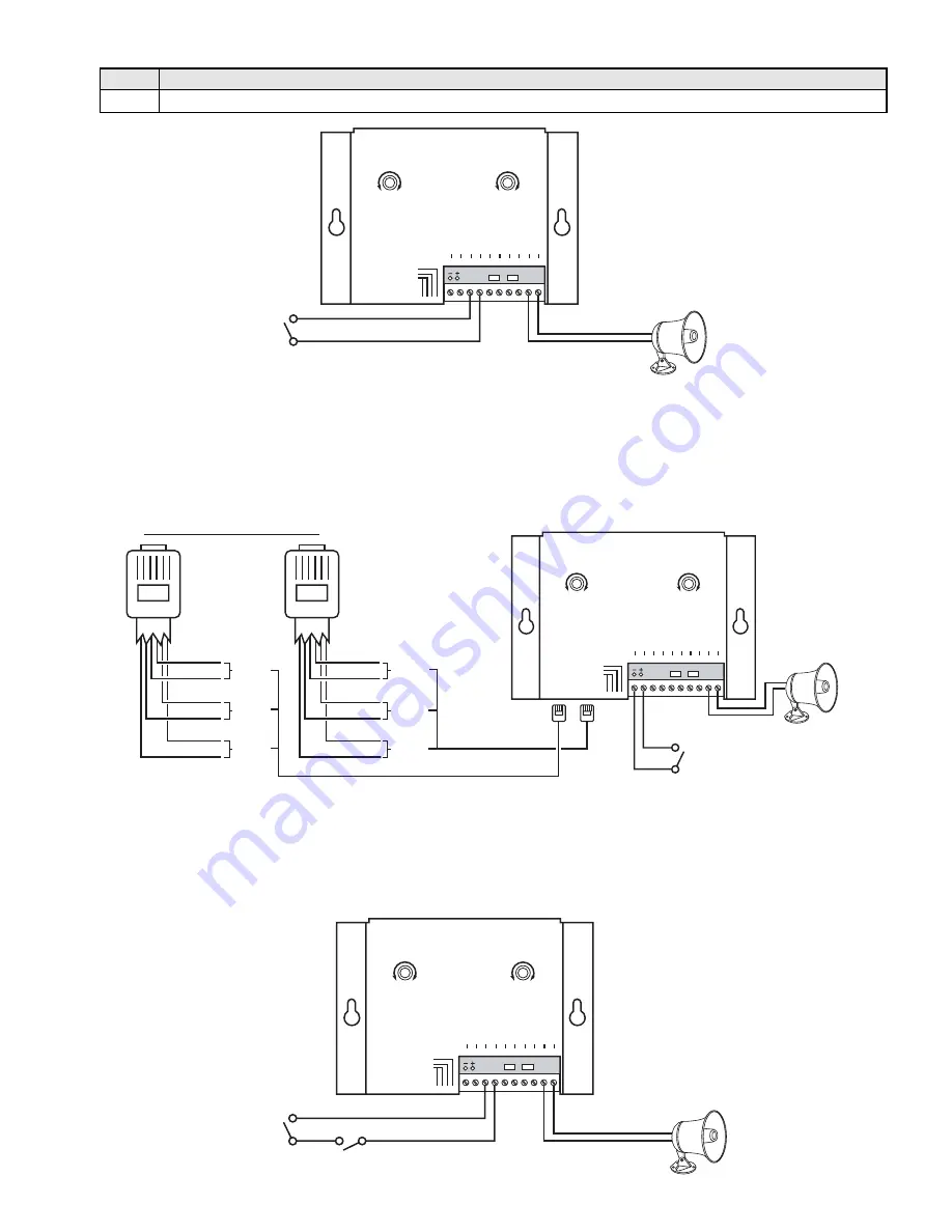
b. Dry Contact Closure with Night Transfer Switch
PAGING - LOUD RINGING
AMPLIFIER SYSTEM
VIKING
ELECTRONICS
HUDSON, WI 54016
VIKING
©
MODEL PA-2A
POWER 13.8V
AC
1 2 3 4 5 6 7 8 9 10
NIGHT TRAN
SFER
SWITCH INPUT
PA
G
ING
HORN
600 OHM
AUDIO OUTPUT
TRUNK / P
AGING
PORT
DR
Y
CONT
ACT
CLOSURE IN
PUT
RINGING
VOLUME
MAX
MIN
1 - 3
4 - 6
RINGING LINES
1 2 3 4
TALK BATTERY
ALERT TONE
WARBLE / CHIME
PAGING
VOLUME
MAX
MIN
POWER
JP1
25AE Paging Horn
(included)
Dry Contact Closure
(not included)
Night Transfer Switch
(not included)
Interface the night transfer switch in series with the contact closure. When the switch is on (closed), loud ring-
ing is enabled. When the switch is off (open), loud ringing is disabled.
2. Dry Contact (Common Audible) Closure (contacts not included)
PAGING - LOUD RINGING
AMPLIFIER SYSTEM
VIKING
ELECTRONICS
HUDSON, WI 54016
VIKING
©
MODEL PA-2A
POWER 13.8V
AC
1 2 3 4 5 6 7 8 9 10
NIGHT TRAN
SFER
SWITCH INPU
T
PA
G
ING
HORN
600 OHM
AUDIO OUTPUT
TRUNK / P
AGING
PORT
DR
Y
CONT
ACT
CLOSURE INPUT
RINGING
VOLUME
MAX
MIN
1 - 3
4 - 6
RINGING LINES
1 2 3 4
TALK BATTERY
ALERT TONE
WARBLE / CHIME
PAGING
VOLUME
MAX
MIN
POWER
JP1
25AE Paging Horn
(included)
Dry Contact Closure
(not included)
A Night Transfer Switch may be used to enable or disable loud ringing.
a. Ringing Analog Lines
3. Night Transfer Switch (switch not included)
PAGING - LOUD RINGING
AMPLIFIER SYSTEM
VIKING
ELECTRONICS
HUDSON, WI 54016
VIKING
©
MODEL PA-2A
POWER 13.8V
AC
1 2 3 4 5 6 7 8 9 10
NIGHT TRAN
SFER
SWITCH INPUT
PA
G
ING
HORN
600 OHM
AUDIO OUTP
UT
TRUNK / P
AGING
PORT
DR
Y
CONT
ACT
CLOSURE INPUT
RINGING
VOLUME
MAX
MIN
1 - 3
4 - 6
RINGING LINES
1 2 3 4
TALK BATTERY
ALERT TONE
WARBLE / CHIME
PAGING
VOLUME
MAX
MIN
POWER
JP1
25AE Paging Horn
(included)
Lines 1, 2 and 3
Lines 4, 5 and 6
Green
Red
Yellow
Black
Blue
White
RJ25
Line 4
Line 5
Line 6
Green
Red
Yellow
Black
Blue
White
RJ25
Line 1
Line 2
Line 3
Lines 1-3
Lines 4-6
Ringing Line Input Wiring
Night Transfer Switch
(not included)
Connect the night transfer switch to terminal pins 1 and 2. When the switch is on (closed), loud ringing is dis-
abled. When the switch is off (open), loud ringing is enabled.
Step 1.
Connect the dry contact closure to pins 3 and 4.
Step 2.
A dry contact closure will initiate loud ringing.
Note:
For information on speak-
ers to use, ambient noise levels
and speaker wiring, see
Fax Back
Document 498
.
Note:
For information on speakers to use, ambient noise levels and speaker wiring, see
Fax Back Document 498
.
Note:
For information on speak-
ers to use, ambient noise levels
and speaker wiring, see
Fax Back
Document 498
.


