background image

© 2010 Viking Preferred Service 

22

Diagnostics

Dispensing Diagnostics Service Tests (cont.)

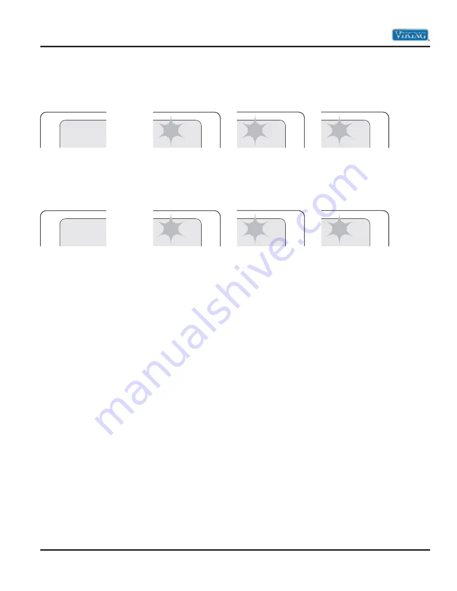
Step 26–Main Control Software Version

Displays in three sequential flashes the dispenser main control software version on digits 3 and 4 at user 
interface display.


00/00/00 

to 


99/99/99

Step 27–Dispenser User Interface Control Software Version

Displays in three sequential flashes the dispenser user interface control software version on digits 3 and 4 at 
user interface display.


00/00/00 

to 


99/99/99

To exit service diagnostics mode perform one of the following:
 

1. Press the “SET” or “RETURN” button for three seconds.


2. Disconnect power to the unit.


3. Unit will automatically exit diagnostic mode after 20 minutes.

Note: 

The controls will resume normal operation to indicate successful exit from service diagnostics mode.

26

Press Both
to activate

03

10

27

Press Both
to activate

03

10

10

10

Summary of Contents for DDSF136D Series

Page 1: ...DVVXPH DQ UHVSRQVLELOLW IRU SURSHUW GDPDJH RU SHUVRQDO LQMXU IRU LPSURSHU VHUYLFH SURFHGXUHV GRQH E DQ XQTXDOL HG SHUVRQ Service Manual This Base Manual covers general and VSHFL F LQIRUPDWLRQ LQFOXGLQJ EXW QRW limited to the following models VCSF136D DDSF136D Freestanding Side by Side Refrigerator Freezer with Dispenser ...

Page 2: ...ousing Heater Status 20 Step 16 Refrigerator Compartment Door Switch Input 20 Step 17 Freezer Compartment Door Switch Input 20 Step 20 Water Filter Usage Rating 20 Description Page Step 21 Water Filter Time Rating 21 Step 22 Water Filter Usage 21 Step 23 Water Filter Time 21 Step 24 Water Filter Reset 21 Step 25 Water Dispensing 21 Step 26 Main Control Software Version 22 Step 27 Dispenser User In...

Page 3: ...L SHEETS BEFORE BEGINNING REPAIRS Pride and workmanship go into every product to provide our customers with quality appliances It is possible however that during the lifetime of a product service may be required Products should be serviced only by a qualified authorized service technician who is familiar with the safety procedures required to perform the repair and is equipped with the proper tools...

Page 4: ... locations This warranty extends to the original purchaser of the product warranted hereunder and to each transferee owner of the product during the term of the warranty This warranty shall apply to products purchased and located in the United States and Canada Products must be purchased in the country where service is requested Warranty labor shall be performed by an authorized Viking Range Corpo...

Page 5: ...on IMPORTANT Retain proof of original purchase to establish warranty period The return of the Owner Registration Card is not a condition of warranty coverage You should however return the Owner Registration Card so that Viking Range Corporation can contact you should any question of safety arise which could affect you Any implied warranties of merchantability and fitness applicable to the described...

Page 6: ...ith grounded 3 prong plug attached to product Maximum amp usage 6 5 amps Inlet water requirements 1 4 copper tubing inlet waterline minimum 30 psi maximum 120 psi Refrigerant Type HFC 134a Refrigerant Charge See rating label Approximate shipping weight 304 lbs 136 8 kg Go to vikingrange com for latest specifications VCSF136D DDSF136D 24 61 0 cm 30 76 2 cm 68 1 2 174 0 cm 71 7 8 182 6 cm with top gr...

Page 7: ...e provided Use an outlet that cannot be turned off by a switch DO NOT use an extension cord IMPORTANT If this product is connected to a GFCI Ground Fault Circuit Interrupter protected outlet nuisance tripping of the power supply may occur resulting in loss of cooling Food quality and flavor may be affected If nuisance tripping has occurred and if the condition of the food appears poor dispose of it...

Page 8: ... for your appliance are located on the identification plate mounted on the upper left side of the door opening Model Numbers Serial Numbers V Professional D Designer F Freestanding 35 Wide 1 Series SS Stainless D Dispenser S Side By Side C Commercial Door D Desinger Door V C S F 1 3 6 D S S Serial Number S04124180 ...

Page 9: ...Ì iÊ refrigerator or freezer first check the air vents to be sure they are not blocked before adjusting the controls UÊÊ Ê iÊ ÀiÃiÌÊÃiÌÌ ÃÊÃ Õ ÊLiÊV ÀÀiVÌÊv ÀÊ À Ê household usage The controls are set correctly when milk or juice is as cold as you like and when ice cream is firm UÊÊ Ê 7 ÌÊ ÌÊ i ÃÌÊÓ Ê ÕÀÃÊLiÌÜii Ê ÕÃÌ i ÌÃ Ê Recheck the temperatures before other adjustments are made UÊÊ Ê Ê iÊ Ã ÞÊÃ...

Page 10: ...en the feature turns on the arrow next to the MAX ICE icon will rotate on the dispenser display The Max Ice setting will remain on for a minimum of 90 minutes unless manually turned off UÊÊ Ê Press OPTIONS a third time to activate Max Cool and Max Ice at the same time When both features are activated both the MAX COOL and MAX ICE arrows will rotate on the dispenser display UÊÊ Ê Ê ÀiÃÃʺ Ê Êv ÕÀÌ ...

Page 11: ...ed on the left hand side of the refrigerator compartment UÊÊ Ê Ê iÊÌ iÊ ÀÊ ÀÊ control to the left to reduce the flow of cold air to the bin or can rack and make it less cold UÊÊ Ê Ê iÊÌ iÊ ÀÊ ÀÊV ÌÀ ÊÌ ÊÌ iÊÀ ÌÊÌ Ê VÀi ÃiÊ the flow of cold air to the bin or can rack and make it colder Water and Ice Dispenser You have the following options the ability to select either crushed or cubed ice a special l...

Page 12: ...enser Pressing hard will not make the ice dispense faster or in greater quantities 3 Remove the glass to stop dispensing Note Ice may continue to dispense for up to 10 seconds after removing the glass from the lever The dispenser may continue to make noise for a few seconds after dispensing The Dispenser Light When you use the dispenser the light will automatically turn on If you want the light to...

Page 13: ...torage bin on the door and push down to make sure it is securely in place Water Filtration System DO NOT use with water that is microbiologically unsafe or of unknown quality without adequate disinfection before or after the system Water Filter Status Light The water filter status light will help you know when to change your water filter When the water filter status display changes from GOOD to ORDER...

Page 14: ... other harsh cleaning tools 1 Unplug refrigerator or disconnect power 2 Hand wash rinse and dry removable parts and interior surfaces thoroughly Use a clean sponge or soft cloth and a mild detergent in warm water 3 Wash stainless steel and painted metal exteriors with a clean sponge or soft cloth and a mild detergent in warm water 4 There is no need for routine condenser cleaning in normal home op...

Page 15: ...controlled in the following manner 1 Evaporator Fan Delay The electronic control delays the evaporator fan from coming on for 60 seconds after the compressor has turned on and the evaporator fan stays on for 90 seconds after the compressor has turned off 2 Pulsed Defrost Heat During the defrost cycle the heater is energized continuously for the first five minutes It is then cycled off for 60 seconds...

Page 16: ...for the dispensing diagnostics Each step must be manually advanced To advance to the next step press the freezer compartment TEMP UP button To return to the previous step press the freezer compartment TEMP DOWN button Diagnostics will begin at step 1 Each step is displayed in the two digits on the left digits 1 and 2 of the dispenser user interface display The steps results are displayed in the tw...

Page 17: ...RC Temp Display Pass Open Short Step 3 Evaporator Fan Motor and Air Baffle Motor Verify the air flow in the baffle changes Not Available Step 4 Condenser Fan Motor Line voltage switched to components from board Verify 120 VAC between line and neutral at motor On Off Step 5 Compressor Set the compressor speed using the RC temp increase to ramp up and RC temp decreases to ramp down Max Speed Min Speed ...

Page 18: ...ically defrost after a minimum of 8 hours of compressor run time and up to a maximum of 96 hours of compressor run time depending on product usage In Basic Mode the unit will automatically defrost after 8 hours of compressor runtime The defrost mode must be set to ADC On before exiting the Service Diagnostic Mode ADC On Basic Mode On 8 hr timer Dispensing Diagnostics Service Tests Step 8 All User ...

Page 19: ...4 COOLING 4 FILTER 3 LOCK 2 OPTIONS 5 Depress the pads in all combinations to verify the appropriate status indicators as shown in the component indicator column Digit 4 displays the status of both water and ice pads Ice pad pressed Water pad pressed Ice and water pad pressed Step 11 Dispensing Light Verify when press RC Temp Up or RC Temp Down buttons the dispenser lighting cycles between maximum...

Page 20: ...ify that the open and close status display correctly Refrigerator Door Refrigerator Door Open Closed Step 17 Freezer Compartment Door Switch Input Displays the freezer compartment door status in real time on digits 3 and 4 of the UI display Verify that the open and close status display correctly Freezer Door Freezer Door Open Closed Step 20 Water Filter Usage Rating Displays in two sequential flash...

Page 21: ... Step 23 Water Filter Time Displays in two sequential flashes the current water filter status in days since the last reset on digits 3 and 4 of the UI display 00 0 to 99 9 Step 24 Water Filter Reset Displays water valve status on digit 4 Initiate water dispenses and verify digit 4 changes to 1 00 0 99 9 Step 25 Water Dispensing Displays water valve status on digit 4 Initiate water dispenses and veri...

Page 22: ...plays in three sequential flashes the dispenser user interface control software version on digits 3 and 4 at user interface display 00 00 00 to 99 99 99 To exit service diagnostics mode perform one of the following 1 Press the SET or RETURN button for three seconds 2 Disconnect power to the unit 3 Unit will automatically exit diagnostic mode after 20 minutes Note The controls will resume normal ope...

Page 23: ... 2010 Viking Preferred Service 23 Parts Location LED Receiver and Emitter Boards Connector Receiver Board LED Board Connector Emitter Board Service Diagnostics and Procedures ...

Page 24: ...4 Parts Location Power Supply and Main Control Boards P8 Connector P10 Connector P7 Connector P13 Connector P1 Connector P4 Connector P3 Connector P5 Connector P11 Connector P1 Connector P2 Connector Service Diagnostics and Procedures ...

Page 25: ...P13 Light Blue Black 01 door open 1 door closed Upper Freezer Light Gemini Flash P4 White Tan to P5 Yellow 12 41 Refrigerator Light Gemini Flash P4 White Tan to P5 Yellow Blue 4 31 5 11 one bulb removed Crisper Light Gemini Flash P4 White Tan to P5 Yellow Blue 4 31 5 11 one bulb removed Ice Maker Water Valve Gemini Flash P5 Tan to P2 White 90 51 Refrigerator Thermistor Gemini Flash P6 Orange to P6...

Page 26: ...ange P11 8 Freezer Thermistor Tan White P11 9 Refrigerator Thermistor Orange P11 10 Refrigerator Thermistor Blue White Pin Number Description Wire Color P5 1 Test terminal Brown P5 2 Refrigerator light Yellow Blue P5 3 Freezer light upper Yellow P5 4 Ice Maker water valve Tan P3 1 In from receiver board Blue Yellow P3 2 Fill tube heater Light Blue P3 3 Test terminal Pink P3 4 Dispenser water valve...

Page 27: ... User interface board Orange Black P10 1 Power Supply Orange Black P10 2 Power Supply Black White P1 1 Condenser fan motor White Red P1 2 Neutral White P1 3 Line in Black P13 1 Ice dispenser motor Blue Black P13 2 Ice dispenser motor Gray Orange P13 3 Light interlock switch Blue P10 1 P10 2 P8 1 P8 2 P8 3 P13 4 P13 5 P13 1 P1 1 P1 3 P1 4 Main Control Board Wiring Connections cont ...

Page 28: ...Emitter Board Pin Number Description Wire Color 1 Ground Blue Yellow 2 Receiver board Brown White 3 Receiver board Orange Black 4 Neutral White Receiver Board Pin Number Description Wire Color 1 Neutral White 3 Light Interlock Switch Yellow 5 Ice Maker Black White 6 Light Interlock Switch Blue Yellow 7 Emitter Board Brown White 8 Emitter Board Orange Black 1 3 5 6 7 8 Power Emitter and Receiver Bo...

Page 29: ...tor 3 2 1 5 Watts 4400 88001 Module Stamped circuit plug in connectors Cycle One revolution ejects ice water fill The table below shows the module ohmmeter checks no power to ice maker ejector blades in park Test Points Component Module Position Ohms L H Mold Heater Attached to support 72 51 see specifications above L M Motor Disconnected from support 8800 The table below shows the module voltage ch...

Page 30: ...nce indicates optics and relay are good but I M is not being sensed will not operate UÊ iV ÊL Ê À ÊÃÜ ÌV Ê ÕÃÌÊLiÊ UÊÊ iV Ê É ÊV ÀVÕ ÌÊ ÊV iVÌ ÃÊL V ÊÌ ÊÌ iÊ receiver board and neutral UÊ iV Ê É ÊV i ÌÃ Two pulses repeated once indicates optics are defective Repeat step one and replace both boards if necessary Steady Light for five seconds indicates the relay and optics are good and the receiver se...

Page 31: ...red Service 31 Service Diagnostics and Procedures Parts Location Refrigerator Compartment Door Switch Temperature Sensor Water Filter Water Tank Meat Vegetable Temperature Control Damper Lower Lights Upper Light Assembly ...

Page 32: ...system designed to filter a flow rate of 0 78GPM and a maximum pressure of 120 PSI To access the water filter 1 Locate water filter Press release button to release filter and pull filter out 2 Turn water filter cap clockwise to remove from water filter 3 Reverse procedure to reinstall Upper Refrigerator Light Bulbs The unit uses standard 40W 120VAC light bulbs to illuminate the upper refrigerator compartm...

Page 33: ...mbly To access the upper light assembly 1 Remove upper refrigerator light bulbs see upper refrigerator light bulb section page 32 2 Remove screws securing upper light assembly 3 Lower light assembly and disconnect wiring 4 Replace or repair as necessary 5 Reverse procedure to reinstall Lower Refrigerator Light Bulbs The unit uses standard 40W 120VAC light bulbs to illuminate the refrigerator compa...

Page 34: ... wiring 3 Slide out damper motor from housing 4 Repair or replace damper 5 Reverse procedure to reinstall WARNING To avoid risk of electrical shock personal injury or death disconnect electrical power to unit using power switch before servicing Wires removed during disassembly must be replaced on proper terminals to insure correct earth ground and polarization After servicing reconnect power using...

Page 35: ...l Water Tank To access the water tank 1 Open door and remove shelves and drawers 2 Remove 1 4 screws securing water tank 3 Disconnect tank and water lines 4 Remove water tank 5 Reverse procedure to reinstall WARNING To avoid risk of electrical shock personal injury or death disconnect electrical power to unit using power switch before servicing Wires removed during disassembly must be replaced on ...

Page 36: ...mbly Vegetable Meat Temperature Control The unit has a slide control to regulate air flow into the vegetable meat drawer To remove control 1 Open doors and remove shelves and drawers 2 Disengage tabs securing cover 3 Remove cover 4 Repair or replace 5 Reverse procedure to reinstall Refrigerator Door Switch To access the refrigerator door switch 1 Open door 2 Use a flat blade to depress light switch ...

Page 37: ...nostics and Procedures Parts Location Freezer Compartment Freezer Panel Emitter Board Upper Freezer Rails Thermistor Ice Maker Defrost Heater Defrost Thermostat Lower Light Receiver Board Air Channel to Refrigerator Upper Light Lower Freezer Rails ...

Page 38: ...rd until they stall out against the ice The motor is designed to stall out and is geared to generate a lot of pressure This minimizes the amount of melting needed to extract the ice As soon as the ice is loose enough to move the ejector pushes the ice out of the mold during the second half of the first revolution During the second revolution the ejector pushes the ice into the bucket To make ice an...

Page 39: ...d approximately 4 75 ounces of water is dispensed If voltage is present and water is not dispensed verify water supply and fill rate Poor water quality can cause ice maker to fail or produce unacceptable cubes Install a water filter to eliminate bad taste odor and visible contaminates Mineral content or sand can restrict screen in water fill valve or particles of sand can keep valve from seating prop...

Page 40: ...ker cont 6 Disconnect ice maker harness 7 Press tabs on wiring harness and push harness through tray assembly 8 Remove 1 4 screws and ice maker tray assembly Thermal Cut Out TCO The TCO is a safety device and must NOT be bypassed If TCO is found to be electrically open the cause must be found and corrected before replacing ice maker The TCO is most likely open if there is no continuity between the...

Page 41: ...d Procedures Disassembly Receiver Board The unit uses a receiver and emitter board to communicate ice maker dispenser functions To access receiver board 1 Open ice maker door 2 Remove phillips screws 3 Lower control into freezer compartment and disconnect wiring 4 Remove phillips screws to remove board 5 Reverse procedure to reinstall Air Channel to Refrigerator 1 Open freezer door and remove ice ...

Page 42: ... Diagnostics and Procedures Disassembly Emitter Board 1 Open ice maker door 2 Remove phillips screws 3 Lower door into freezer compartment and disconnect wiring 4 Remove phillips screws to remove board 5 Reverse procedure to reinstall Upper Freezer Light Bulb The unit uses a standard 40W 120VAC light bulb to illuminate the upper freezer compartment To access the upper light bulb 1 Remove Ice maker...

Page 43: ...mbly Freezer Thermistor The unit use a NTC sensor to regulate temperature in the freezer compartment To access the thermistor 1 Open door and remove basket 2 Remove 1 4 securing screw 3 Disconnect wiring and remove sensor 4 Repair or replace sensor 5 Reverse procedure to reinstall Lower Freezer Light bulb The unit uses a standard 40W 120VAC light bulb to illuminate the lower freezer compartment To...

Page 44: ...ower switch Service Diagnostics and Procedures Disassembly Freezer Drawer To access 1 Open drawer fully and press down on front of drawer to release basket side frame from rail channel 2 Slide drawer out and remove 3 Reverse procedure to reinstall Upper Freezer Rails To access 1 Remove freezer drawer see freezer drawer section at left 2 Open rail fully and remove back securing screw 3 Rotate sligh...

Page 45: ...ground and polarization After servicing reconnect power using power switch Service Diagnostics and Procedures Disassembly Lower Freezer Rails To access 1 Remove drawer see freezer drawer section page 44 2 Remove securing screws and lower rails 3 Reverse procedure to reinstall Upper Back Panel To access 1 Open freezer door and remove shelves 2 Remove upper back panel by pulling out at the bottom an...

Page 46: ...move upper back panel see upper back panel section page 45 4 Remove 1 4 securing screws and panel 5 Reverse procedure to reinstall Note With the freezer panel removed the evaporator fan defrost heater and defrost thermostat are accessible Evaporator Fan The unit uses a fan motor to pull air over the evaporator coil and circulate it throughout the unit Evaporator Fan access 1 Open freezer door and ...

Page 47: ...during the defrost cycle When the defrost terminator closes voltage is supplied to the heater via the control board Defrost Heater access 1 Open freezer door and remove shelves basket and drawers see freezer drawer page 44 2 Remove basket supports upper and lower freezer rails see upper and lower freezer rail sections pages 44 45 3 Remove upper back panel see upper back panel section page 45 4 Rem...

Page 48: ...es into defrost mode the thermostat closes supplying power to the defrost heater Once the freezer section reaches 35 F the terminator opens and power to the heater is broken Defrost Thermostat access 1 Open freezer door and remove shelves basket and drawers see freezer drawer page 44 2 Remove basket supports upper and lower freezer rails see upper and lower freezer rail sections pages 44 45 3 Remo...

Page 49: ... 2010 Viking Preferred Service 49 Service Diagnostics and Procedures Parts Location Dispenser User Interface Board LED Assembly Ice Guide Ice Paddle Assembly Water Paddle Assembly Water Fitting ...

Page 50: ...earth ground and polarization After servicing reconnect power using power switch Service Diagnostics and Procedures Disassembly Dispenser Bezel 1 Press tabs with blade to disengage bezel assembly from dispenser housing 2 Lift bezel assembly up and out 3 Disconnect wiring from user interface board 4 From inside of bezel remove two screws to release user interface board 5 Repair or replace user inte...

Page 51: ...d Procedures Disassembly Dispenser LED Board 1 Remove dispenser bezel see dispenser bezel section steps 1 3 page 50 2 Disengage tabs to remove LED board from control bracket 3 Repair or replace user LED board 4 Reverse procedure to reinstall Water Fitting Ice Guide Ice and Water Paddle Assemblies 1 Remove dispenser bezel see dispenser bezel section steps 1 3 page 50 2 Remove grounding screw 3 Disc...

Page 52: ...ization After servicing reconnect power using power switch Service Diagnostics and Procedures Disassembly Water Fitting Ice Guide Ice and Water Paddle Assemblies cont 4 Remove right screw and slide tube out to remove water fitting 5 Disconnect delay and remove ice guide by pulling outward 6 Remove center screw and retainer to remove ice and water paddle assemblies 7 Repair or replace 8 Reverse proc...

Page 53: ... 2010 Viking Preferred Service 53 Service Diagnostics and Procedures Disassembly Parts Location Rear Control Board Power Board Condenser Fan Water Valve Inverter ...

Page 54: ...it uses a power inverter to convert the AC line signal to a 24V DC signal to operate the compressor To access inverter 1 Slide unit out for service Remove securing screws and lower rear cover 2 Remove Inverter securing screws and disconnect wiring 3 Repair or replace inverter 4 Reverse procedure to reinstall Condenser Fan Need description 1 Slide unit out of service Remove securing screws and lowe...

Page 55: ...fter servicing reconnect power using power switch Service Diagnostics and Procedures Disassembly Main Control Board To access main control board 1 Slide unit out of service Remove securing screws and lower rear cover see inverter section step 1 page 54 2 Remove screws and control box housing 3 Lift off the housing cover 4 Disconnect wiring Press tabs to release main control board 5 Repair or repla...

Page 56: ...r supply line is ON water pressure is not below 20 psi and saddle valve is fully open Clear restrictions by fully closing and opening valve dislodge sediment if necessary remove valve and enlarge pierced hole to 3 16 diameter with a drill and reinstall saddle valve Make sure water line to unit is not pinched kinked clogged ice is not present in inlet tube blocking water flow and water pressure is n...

Page 57: ...ration Unit will not operate Power Supply Circuit Breaker Power Switch Verify voltage Reset breaker Turn to the on position Ice maker will not operate Freezer too warm Shut off arm Water valve Water supply Verify freezer temperature Verify the arm is in the ON position Verify valve operation Verify water supply Refrigerator too warm Door opening Warm food placed in unit Control setting Door seal A...

Page 58: ...ing Door seal Dirty condenser Condenser evaporator fan Control board Move to medium setting Verify closure replace if needed Clean condenser coil Verify movement operation of fan Verify operation Frost on evaporator Defrost thermostat Evaporator fan Defrost heater Verify thermostat is closing Check connection and possible short open condition Verify heater is not open ...

Page 59: ...ion No water to refrigerator Turn on supply Look for obstructions in supply line or valve No water to ice maker Look for obstructions in water valve or fill tube Clogged water valve Clean or replace water valve depending on type Insufficient water to ice maker with correct fill time Check for restrictions in supply line and valve especially saddle valves Low water pressure at supply Increase water pr...

Page 60: ...ion Ice maker not level Check level of refrigerator first then level Ice maker Can t level Ice maker Level refrigerator first then try again Open thermostat won t close below 17 F Replace thermostat Closed thermostat won t open above 32 F Replace thermostat Thermostat out of calibration Replace thermostat Heater not staked in mold Replace ice maker Won t cycle test with power available Replace ice m...

Page 61: ... 2010 Viking Preferred Service 61 Wiring and Schematics Full Schematic ...

Page 62: ... 2010 Viking Preferred Service 62 Wiring and Schematics Wiring Diagram ...

Reviews: