11
WARNING:
To avoid electrical shock which can cause severe personal injury or death,
disconnect power to refrigerator using power switch before servicing. Wires removed during
disassembly must be replaced on proper terminals to insure correct earth ground and polarization.
After servicing, reconnect power using power switch.
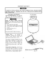
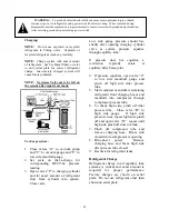
Charging:
NOTE:
Do not use captured or recycled
refrigerant in Viking units. Captured or
recycled refrigerant voids any warranty.
NOTE:
Charge system with exact amount
of refrigerant. See Technical Sheet or refer
to unit serial plate for correct refrigerant
charge. Inaccurately charged system will
cause future problems.
NOTE: No Access Valve are to be left on
the system after repairs are made.
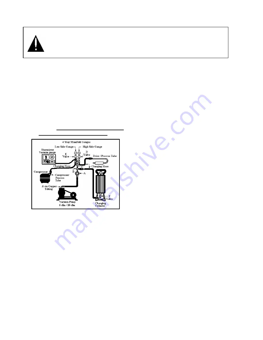
To charge system:
1.
Close valves “A” to vacuum pump
and “C” to vacuum gauge and “E” to
low side manifold gauge.
2.
Set scale on dial-a-charge for
corresponding HFC134a pressure
reading.
3.
Open valves “F” to charging cylinder
and let exact amount of refrigerant
flow from cylinder into system.
Close valve.
Low side gauge pressure should rise
shortly after opening charging cylinder
valve as system pressure equalize
through capillary tube.
If pressure does not equalize, a
restriction typically exists at
capillary/drier braze joint.
4.
If pressure equalizes, open valve “E”
to low side manifold gauge and
pinch off high side drier process
tube.
5.
Start compressor and draw remaining
refrigerant front charging hoses and
manifold into compressor through
compressor process tube.
6.
To check high side, pinch off drier
process tube. Close valve “D” to
high side gauge. If high side
pressure rises, repeat high side pinch
off and open valve “D”. repeat until
high side pinch off does not leak.
7.
Pinch off compressor tube and
remove charging hose. Braze stub
closed while compressor is opening.
8.
Disconnect power. Remove
charging hose and braze high side
drier process tube closed.
9.
Recheck for refrigerant leaks.
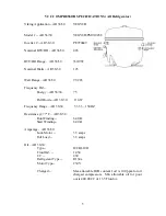
Refrigerant Charge
Refrigerant charge in all capillary tube
systems is critical and exact amount is
required for proper performance.
Factory charges are shown on serial
plate. Do not use refrigerant other than
shown on serial plate.
Summary of Contents for Designer DDFB304
Page 1: ...F90612...
Page 2: ...F90612 VIKING RANGE CORPORATION P O DRAWER 956 GREENWOOD MS 38930 USA...
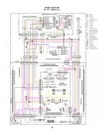
Page 22: ...21 Wiring Schematic 30 W All Freezer...
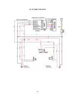
Page 23: ...22 AF 30 LIGHT CIRCUITS...
Page 24: ...23 AF 30 120V CIRCUIT...
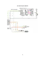
Page 25: ...24 AF 30 SEALED SYSTEM...
Page 26: ...25 AF 30 ICEMAKER CIRCUIT...
Page 27: ...26 Wiring Schematic 36 W All Freezer...
Page 28: ...27 AF 36 LIGHT CIRCUITS...
Page 29: ...28 AF 36 120V CIRCUIT...
Page 30: ...29 AF 36 SEALED SYSTEM...
Page 31: ...30 AF 36 ICEMAKER CIRCUIT...
Page 32: ...31 Wiring Schematic 30 W All Refrigerator...
Page 33: ...32 AR 30 120V INPUT AR 30 LIGHT CIRCUITS...
Page 34: ...33 AR 30 SEALED SYSTEM...
Page 35: ...34 Wiring Schematic 36 W All Refrigerator...
Page 36: ...35 AR 36 120V INPUT AR 36 LIGHT CIRCUITS...
Page 37: ...36 AR 36 SEALED SYSTEM...
Page 39: ...38 ALL MODELS New Control Boards with adapter functionality...
Page 40: ...39...
Page 48: ...47 SEALED SYSTEM...


