15
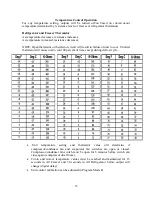
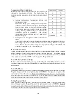
Temperature Control Operation
For any temperature setting, outputs will be turned off/on based on cut-in/cut-out
temperature determined by resistance levels of freezer or refrigerator thermistors
Refrigerator and Freezer Thermistor
As temperature decreases, resistance increases.
As temperature increased, resistance decreases.
NOTE: Open thermistor or thermistor circuit will result in failure of unit to cool. Shorted
thermistor will cause unit to run 100 percent of time except during defrost cycle.
•
.Unit temperature setting and thermistor value will determine if
compressor/condenser fan and evaporator fan switches are open or closed.
Compressor/condenser fan switch must be open for 6 minutes before switch can
close again (compressor dwell time).
•
Cut-in and cut-out temperature values must be reached and maintained for 15
seconds in All Freezer and 30 seconds in All Refrigerator before output will
change (digital delay).
•
Unit control calibration can be adjusted in Program Mode B.
Summary of Contents for Designer DDFB304
Page 1: ...F90612...
Page 2: ...F90612 VIKING RANGE CORPORATION P O DRAWER 956 GREENWOOD MS 38930 USA...
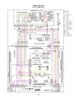
Page 22: ...21 Wiring Schematic 30 W All Freezer...
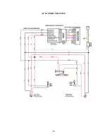
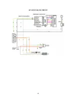
Page 23: ...22 AF 30 LIGHT CIRCUITS...
Page 24: ...23 AF 30 120V CIRCUIT...
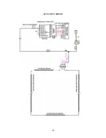
Page 25: ...24 AF 30 SEALED SYSTEM...
Page 26: ...25 AF 30 ICEMAKER CIRCUIT...
Page 27: ...26 Wiring Schematic 36 W All Freezer...
Page 28: ...27 AF 36 LIGHT CIRCUITS...
Page 29: ...28 AF 36 120V CIRCUIT...
Page 30: ...29 AF 36 SEALED SYSTEM...
Page 31: ...30 AF 36 ICEMAKER CIRCUIT...
Page 32: ...31 Wiring Schematic 30 W All Refrigerator...
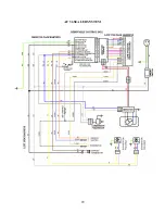
Page 33: ...32 AR 30 120V INPUT AR 30 LIGHT CIRCUITS...
Page 34: ...33 AR 30 SEALED SYSTEM...
Page 35: ...34 Wiring Schematic 36 W All Refrigerator...
Page 36: ...35 AR 36 120V INPUT AR 36 LIGHT CIRCUITS...
Page 37: ...36 AR 36 SEALED SYSTEM...
Page 39: ...38 ALL MODELS New Control Boards with adapter functionality...
Page 40: ...39...
Page 48: ...47 SEALED SYSTEM...


