background image


42

NORMAL OPERATION 

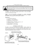
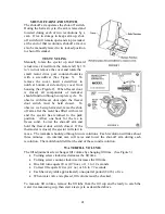
The icemaker always starts from and stops at the “park” position.  In the park position the 
ejector blades are pointing horizontally towards the back of the icemaker.  Just before 
reaching the park position the mold is filled with water.  At the park position all electrical 
components are de-energized, even though the shut-off arm is down, and the icemaker is 
ready for the next freeze cycle. 

The icemaker takes from 30 minutes to one hour to freeze the water.  The primary time 
factors are the temperature in the freezer and the amount of airflow around the icemaker.  
Colder freezer settings and free air space around the icemaker to let air circulate will help 
make ice faster. 

After the ice forms, the icemaker continues to wait until it reaches 15º F before it starts 
the harvest cycle.  This insures that the ice is solid in all the cavities.  At 15º F the 
thermostat closes, the mold heater turns on, and the ejector blades rotate up and forward 
until they stall out against the ice.  The motor is designed to stall out and is geared to 
generate a lot of pressure.  This minimizes the amount of melting needed to extract the 
ice.  As soon as the ice is loose enough to move, the ejector pushes the ice out of the 
mold during the second half of the first revolution.  During the second revolution the 
ejector pushes the ice into the bucket.  Just before the ejector completes the second 
revolution the icemaker turns the water valve on for approximately 7 seconds and refills 
the mold with approximately 4 ounces of water and the freezing cycle is ready to begin 
again. 

TROUBLESHOOTING 

Replace if necessary….

BUT DON’T REPLACE UNTIL YOU ARE SURE IT IS 

THE ICEMAKER.  

Here’s how to tell:  To make ice, an icemaker needs power, water, 

and sub-freezing temperatures. 

ELECTRICAL POWER 

NOTE: The freezer door switch turns off power to the icemaker when the freezer door is 
open.  It will be necessary to manually close the freezer door switch for some 
troubleshooting steps. 

1.


Check that the shut-off arm is down and instruct customer on its use if 
necessary. 

2.


Quick check for power without a test device.  Manually rotate the ejector up 
and forward (clockwise viewed from the motor end) by 1/8 to 1/4 turn or 
remove the cover and rotate the small motor drive gear counter-clockwise 
with a screwdriver.  With hands clear of the icemaker, manually close the 
freezer door switch.  If the ejector begins to rotate (very slowly) there is 
power.  If the ejector does not rotate, go on to Step 3. 

3.


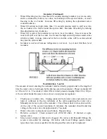
Checking for power with a test device: See figure 4.  unplug the icemaker and 
connect a test light or a voltmeter to the top and bottom terminals of the 4-
pole connector socket.  Manually close the freezer door switch.  If there is 
power, check for water next.  If there is not power at the icemaker connector, 
trace power from the wall socket to the door switch to the connector.  (Con’t) 

Summary of Contents for Designer DDFB304

Page 1: ...F90612...

Page 2: ...F90612 VIKING RANGE CORPORATION P O DRAWER 956 GREENWOOD MS 38930 USA...

Page 3: ...Freezer 21 30 All Freezer 120V Supply and Light Circuit 22 30 All Freezer Sealed System 23 30 All Freezer Icemaker 24 36 Wide All Freezer 25 36 All Freezer 120V Supply and Light Circuit 26 36 All Fre...

Page 4: ...rvicing reconnect power using power switch General Specifications Model FB304 RB304 FB364 RB364 Internal Volume Capacity cu Ft 15 9 18 2 19 1 22 8 Electrical Requirements 9 1 amps 5 7amps 9 5amps 6 5a...

Page 5: ...4 197 Frequency HZ Energy AF 36 30 75 Pull Down AF 36 30 114 67 Frequency Range AF 36 30 53 33 150 HZ Resistance 77 F AF 36 30 Run Winding 6 40 Start Winding 6 40 Amperage AF 36 30 Lock Motor 3 3 amps...

Page 6: ...7 283 Frequency HZ Energy AR 36 30 75 Pull Down AR 36 30 114 67 Frequency Range AR 36 30 53 33 150 HZ Resistance 77 F AR 36 30 Run Winding 6 40 Start Winding 6 40 Amperage AR 36 30 Lock Motor 3 3 amps...

Page 7: ...unlight or in a damp location Heat the tank above 125 F Refill the tank Empty tanks should be disposed of properly ILLUSTRATION Charging Scale An electronic or computerized charting scale measures the...

Page 8: ...he need for brazing and will not remain on the system when repairs are completed Fig 5 Process Tube Adaptor Kit This kit allows the attachment of hand valves to various sizes of exposed tubing ends du...

Page 9: ...MC Size Fuel Tank of Acetylene with a Double Tip Torch The MC size single fuel tank of acetylene gas is very portable and easy to use Two torches are acceptable for use A double tip torch heats both...

Page 10: ...score capillary tubing A steel brush will be required to clean brazed joints Fig 14 Heat Trap Paste Heat trap paste should be applied to the tubing between the brazing site and the components or area...

Page 11: ...uation To evacuate sealed refrigeration system 1 Connect vacuum pump vacuum tight manifold set with high vacuum hoses thermocouple vacuum gauge and charging cylinder as shown in illustration Evacuatio...

Page 12: ...t flow from cylinder into system Close valve Low side gauge pressure should rise shortly after opening charging cylinder valve as system pressure equalize through capillary tube If pressure does not e...

Page 13: ...ge freezer temperature setting by pressing Higher or Lower pad Ref Temp Pad Activates refrigerator temperatures setting mode Shown only on All Refers 1 Refrigerator indicator light will glow Refrigera...

Page 14: ...eezer duration refer to Program Mode B functions 4 Used to enter Program Mode See Hidden Pad Max Ref Pad Activates Maximum refrigerator mode setting refrigerator to coldest setting Current factory set...

Page 15: ...s open more than 3 minutes 1 Turn off Door Open alarm by pressing Alarm Off pad or by closing door 2 Deactivate Door Open alarm by pressing Activate Controls pad and then press hold Alarm Off pad for...

Page 16: ...re of unit to cool Shorted thermistor will cause unit to run 100 percent of time except during defrost cycle Unit temperature setting and thermistor value will determine if compressor condenser fan an...

Page 17: ...will illuminate 6 Toggle to Program Mode B by pressing Activate Controls pad Unmarked indicator light is off EEPROM Update in Control Memory EEPROM is permanent programmable memory of the control boar...

Page 18: ...resent delay setting in minutes indicator 1 means 1 minute 2 means 2 minutes etc Default delay is 3 minutes 2 Press Higher pad to decrease delay by 1 minute 3 Press Lower pad to increase delay by 1 mi...

Page 19: ...or conventional defrost mode Hidden Button indicator glows when adaptive defrost has bee selected If Hidden Button indicator is off conventional defrost is selected Conventional defrost uses 8 hour C...

Page 20: ...gain Holiday Mode Feature for Sabbath Observance Before the Holiday Mode is engaged the bale arm of the ice maker needs to be raised until it clicks into the detent This turns off the power to the ice...

Page 21: ...ned on by putting it into a forced pull down using the methods that were intended only for normal and program modes In Sabbath Mode If the door is open and the power is lost the cabinet lights will bl...

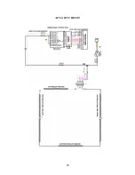
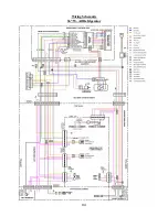
Page 22: ...21 Wiring Schematic 30 W All Freezer...

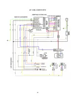
Page 23: ...22 AF 30 LIGHT CIRCUITS...

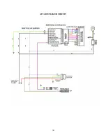
Page 24: ...23 AF 30 120V CIRCUIT...

Page 25: ...24 AF 30 SEALED SYSTEM...

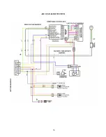
Page 26: ...25 AF 30 ICEMAKER CIRCUIT...

Page 27: ...26 Wiring Schematic 36 W All Freezer...

Page 28: ...27 AF 36 LIGHT CIRCUITS...

Page 29: ...28 AF 36 120V CIRCUIT...

Page 30: ...29 AF 36 SEALED SYSTEM...

Page 31: ...30 AF 36 ICEMAKER CIRCUIT...

Page 32: ...31 Wiring Schematic 30 W All Refrigerator...

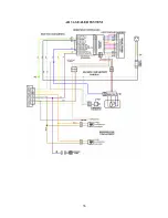
Page 33: ...32 AR 30 120V INPUT AR 30 LIGHT CIRCUITS...

Page 34: ...33 AR 30 SEALED SYSTEM...

Page 35: ...34 Wiring Schematic 36 W All Refrigerator...

Page 36: ...35 AR 36 120V INPUT AR 36 LIGHT CIRCUITS...

Page 37: ...36 AR 36 SEALED SYSTEM...

Page 38: ...cause severe personal injury or death disconnect power to unit using power switch before servicing Wires removed during disassembly must be replaced on proper terminals to insure correct earth ground...

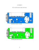
Page 39: ...38 ALL MODELS New Control Boards with adapter functionality...

Page 40: ...39...

Page 41: ...NFORMATION IS DESIGNED TO ASSIST QUALIFIED PERSONNEL ONLY UNQUALIFIED PERSONS SHOULD NOT ATTEMPT REPAIRS DUE TO POSSIBILITY OF ELECTRICAL SHOCK Specifications Use SxS Style Icemaker only Electrical 11...

Page 42: ...se the shut off arm after the mold has filled with water and the ejector has returned to the park position Allow one hour for the ice to freeze solid Lower the shut off arm and hold the freezer door s...

Page 43: ...e ice into the bucket Just before the ejector completes the second revolution the icemaker turns the water valve on for approximately 7 seconds and refills the mold with approximately 4 ounces of wate...

Page 44: ...ict saddle valves WATER SUPPLY 1 Water supply is turned OFF Turn water supply line ON 2 Water pressure too low below 20 psi Check pressure at source If OK look for obstructions or restrictions as foll...

Page 45: ...f water entering the icemaker mold is directly proportional to the length of time the water valve is held open by the timing cam in the icemaker Proper icemaker fill is 120cc at 6 6 to 7 2 seconds of...

Page 46: ...n the mold it will only complete half a revolution and then stall out against the ice 2 Freezer too warm Check temperature in freezer If temperature is appropriate for setting go to a lower setting le...

Page 47: ...ssure to 20 120 psi Low water pressure at water valve Look for restrictions in line Excessive water pressure Install pressure regulator and set to 60 psi Low water fill volume Adjust water fill screw...

Page 48: ...47 SEALED SYSTEM...

Reviews: