7
EQUIPMENT DESCRIPTION
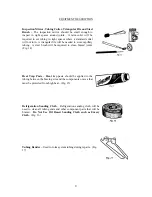
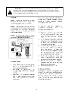
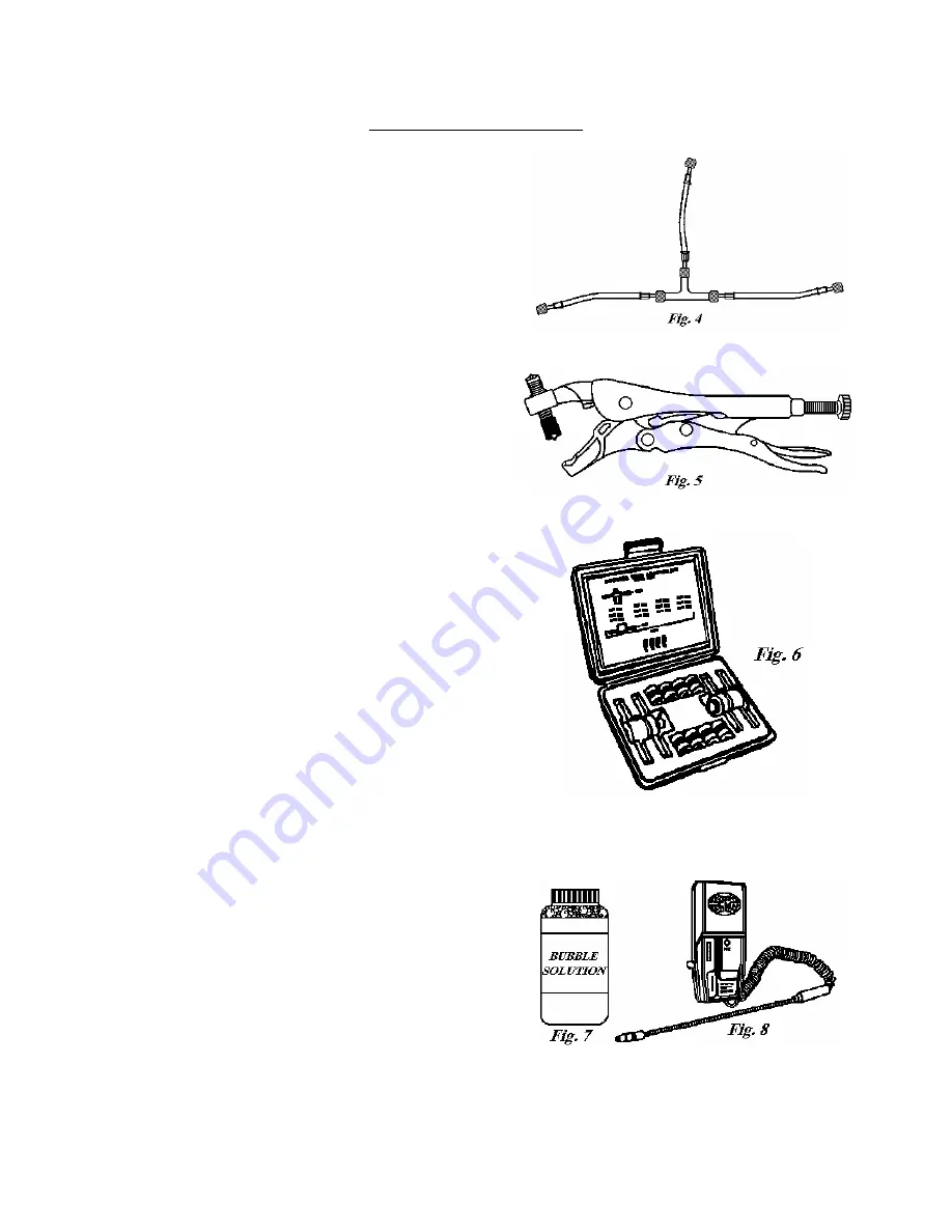
Purging Hose Configuration –
This arrangement of three
4’ to 6’ hoses with low-loss fittings and a ¼” male flare
Tee fitting can be used to purge a sealed system for both
operating and non-operating compressor situations. No
hand valves are required. (Fig. 4)
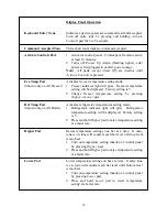
Piercing Tool with Access Valve –
These access valves
can be installed without the need for brazing and
will
not
remain on the system when repairs are completed.
(Fig. 5)
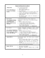
Process Tube Adaptor Kit –
This kit allows the attachment of
hand valves to various sizes of exposed tubing ends during back
flushing, charging, and/or evacuating a sealed system. (Fig. 6)
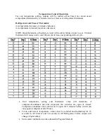
Bubble Solution or Electronic Leak Detector –
Bubble
solution is the recommended means of checking for high-
side leaks after repairing a pressurized sealed system. (Fig.
7) An electronic leak detector will also detect the presence
of any refrigerant escaping from the sealed system. (Fig. 8)
Summary of Contents for Designer DDFB304
Page 1: ...F90612...
Page 2: ...F90612 VIKING RANGE CORPORATION P O DRAWER 956 GREENWOOD MS 38930 USA...
Page 22: ...21 Wiring Schematic 30 W All Freezer...
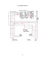
Page 23: ...22 AF 30 LIGHT CIRCUITS...
Page 24: ...23 AF 30 120V CIRCUIT...
Page 25: ...24 AF 30 SEALED SYSTEM...
Page 26: ...25 AF 30 ICEMAKER CIRCUIT...
Page 27: ...26 Wiring Schematic 36 W All Freezer...
Page 28: ...27 AF 36 LIGHT CIRCUITS...
Page 29: ...28 AF 36 120V CIRCUIT...
Page 30: ...29 AF 36 SEALED SYSTEM...
Page 31: ...30 AF 36 ICEMAKER CIRCUIT...
Page 32: ...31 Wiring Schematic 30 W All Refrigerator...
Page 33: ...32 AR 30 120V INPUT AR 30 LIGHT CIRCUITS...
Page 34: ...33 AR 30 SEALED SYSTEM...
Page 35: ...34 Wiring Schematic 36 W All Refrigerator...
Page 36: ...35 AR 36 120V INPUT AR 36 LIGHT CIRCUITS...
Page 37: ...36 AR 36 SEALED SYSTEM...
Page 39: ...38 ALL MODELS New Control Boards with adapter functionality...
Page 40: ...39...
Page 48: ...47 SEALED SYSTEM...


