background image


45

Summary of Contents for DFSB483D

Page 1: ...VCSB483D DFSB483D DDSB483D COVER F90597...

Page 2: ...SERVICE NOTEBOOK REFRIGERATION VCSB483D DFSB483D DDSB483D VIKING RANGE CORPORATION P O DRAWER 956 GREENWOOD MS 38930 USA F90597...

Page 3: ...rd Check Points 26 Wiring Diagram VCSB483 no Water or Ice in door Dispenser 27 Wiring Diagram VCSB483D Dispenser Model 28 Variable Capacity Compressor VCC Control Unit 29 Speed Control Interface 30 Wi...

Page 4: ...VCSB483D with ICE and WATER 4...

Page 5: ...CABINET AIR FLOW 5...

Page 6: ...MACHINE COMPARTMENT AIR FLOW 6...

Page 7: ...REFRIGERANT FLOW 7...

Page 8: ...WATER FLOW 8...

Page 9: ...ath disconnect power to refrigerator using power switch before servicing Wires removed during disassembly must be replaced on proper terminals to insure correct grounding and polarization After servic...

Page 10: ...wn to control temperature The compressor duty cycle exceeds DCHT 90 Once triggered this mode persists until the duty cycle drops below DCHX 50 A high external ambient increases the duty cycle Compress...

Page 11: ...OMPRESSOR Get another one The filter drier MUST be cut from the sealed system Never un braze the filter drier from system tubing Applying heat will drive moisture back into the sealed system HEALTH AN...

Page 12: ...osely release refrigerants into the environment Inhale refrigerant vapors Use refrigerant in a unventilated area Allow refrigerant to contact your skin eyes or clothing SAFETY INFORMATION If refrigera...

Page 13: ...direct sunlight or in a damp location Heat the tank above 125 F Refill the tank Empty tanks should be disposed of properly Charging Scale An electronic or computerized charting scale measures the amou...

Page 14: ...need for brazing and will not remain on the system when repairs are completed Fig 5 Process Tube Adaptor Kit This kit allows the attachment of hand valves to various sizes of exposed tubing ends duri...

Page 15: ...uel Tank of Acetylene with a Double Tip Torch The MC size single fuel tank of acetylene gas is very portable and easy to use Two torches are acceptable for use A double tip torch heats both sides of t...

Page 16: ...re capillary tubing A steel brush will be required to clean brazed joints Fig 14 Heat Trap Paste Heat trap paste should be applied to the tubing between the brazing site and the components or area tha...

Page 17: ...uum pump can only Moisture in sealed system chemically reacts with refrigerant and oil to form corrosive hydrofluoric and hydrochloric acids These acids attack motor windings and parts causing prematu...

Page 18: ...low from cylinder into system Close valve Low side gauge pressure should rise shortly after opening charging cylinder valve as system pressure equalize through capillary tube If pressure does not equa...

Page 19: ...temperature setting mode 1 Freezer indicator light will glow Freezer temperature setting will be displayed Factory setting is 5 2 Change freezer temperature setting by pressing Higher Temp or Lower Te...

Page 20: ...ess pad 4 Within 6 seconds press the following pads in this sequence Max Ref Max Frz Max Ref Max Frz 5 Tone will sound 3 times and control will be in program mode A Display Off Pad 1 Deactivates contr...

Page 21: ...ontrol calibration can be adjusted in Program Mode B Factory set freezer and refrigerator settings See page 24 Item B Adaptive Defrost Operation Defrost occurs after predetermined length of compressor...

Page 22: ...stor Temperature 1 Choose Refrigerator Thermistor temperature display by pressing Ref Temp pad 2 Refrigerator thermistor temperature displays Mode B Functions Automatic Keyboard Functions Activate and...

Page 23: ...olding the Alarm Off pad for 3 seconds Program changes will be saved permanently in EEPROM and program mode will exit to Run Mode Forced Pull Down Compressor start can be forced by pressing and holdin...

Page 24: ...Refrigerator Freezer Thermister ITEM A Reading Temperature Display ITEM C Factory Set Freezer Refrigerator ITEM B Temperature Offset Calibration ITEM D 24...

Page 25: ...use severe personal injury or death disconnect power to refrigerator using power switch before servicing Wires removed during disassembly must be replaced on proper terminals to insure correct earth g...

Page 26: ...an motor relay CLOSED R8 to ground approximately 11VDC OPEN R8 to ground approximately 25VDC Evaporator fan motor ON E2 Neutral or ground approximately 115VAC OFF E2 Neutral or ground 0VAC Defrost hea...

Page 27: ...VCSB483 WIRING DIAGRAM 27 27...

Page 28: ...VCSB483D WIRING DIAGRAM DISPENSER MODEL 28...

Page 29: ...the refrigerator The meter should see the two frequencies called out in the Adapter board drawing The frequencies will fluctuate every 15 seconds until the time reaches 45 seconds 15 30 45 sec The fre...

Page 30: ...GE SYMBOL Min Type Max Unit HIGH Vhigh 4 5 5 0 5 5 V LOW Vlow 0 2 0 0 2 V REVERSE VOLTAGE VR 6 V ISOLATION VOLTAGE AC for 1 min Viso 5 V FORWARD CURRENT IF 3 5 10 mA REVERSE CURRENT IR 10 A The pulse...

Page 31: ...onal injury or death disconnect power to refrigerator using power switch before servicing Wires removed during disassembly must be replaced on proper terminals to insure correct earth ground and polar...

Page 32: ...nals one to the compressor relay coil C1 and one to the evaporator relay coil E1 When both relay coils are energized and both relay contacts are closed high voltage circuits to evaporator fan motor co...

Page 33: ...r and condenser fan motor and for operation of the fresh food fans Once the signal is sent for operation of the compressor the adapter board sends a 3mA 5VDC square wave frequency signal to the invert...

Page 34: ...ntrol Section and the electronic signals for compressor condenser fan motor operation and for operation of fresh food fan See previous section on Freezer and Refrigeration Compartment Theory of Operat...

Page 35: ...no equalized pressure between suction and discharge sides in the refrigerating system The inverter will also assume a waiting condition if hardware defects are detected before the first try e If power...

Page 36: ...assume a waiting condition depending on the software version installed this situation may be encountered if there is no equalized pressure between suction and discharge sides in the refrigerating syst...

Page 37: ...h SHORT CIRCUIT PROTECTON In case short circuits a current detection circuit will open the power switches cutting the current and avoiding further damage to power devices or compressor winding In cas...

Page 38: ...CONTROL BOARD OPERATION 38...

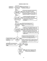
Page 39: ...TROUBLESHOOTING 39...

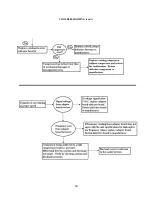
Page 40: ...TROUBLESHOOTING con t 40...

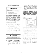
Page 41: ...shaped cubes to e bucket e Dispense water by pressing sturdy wide mouthed con water dispenser pad Stop water dispensing by releasing pressure on pad A small amount of water may continue to fall Spill...

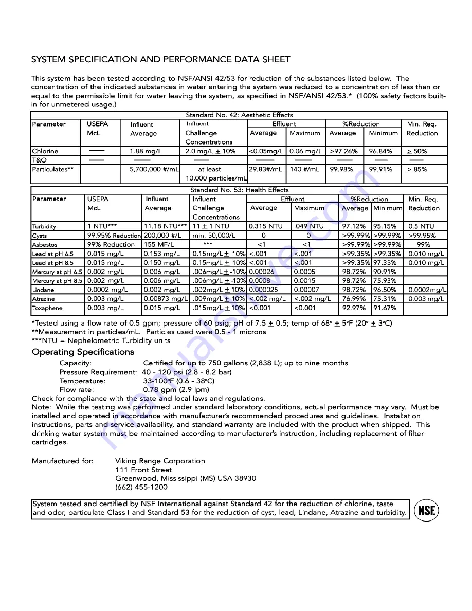
Page 42: ...NSTALLATION NOTE If the system will not be used for an extended period of time turn water off Removing the cartridge and storing it in a sealed plastic bag in the refrigerator will reduce loss of life...

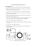
Page 43: ...Union 5 Remove nuts and ferrules from Water Filter Union and slide onto open ends of Water Filter Inlet Line and Water Supply Line 6 Connect nuts on copper tubing to Water Filter Union Be sure both n...

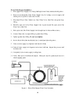
Page 44: ...lide open end of the Water Supply Line through brass ferrule and brass sleeve 6 Connect brass nuts on copper tubing to garden hose fitting 7 Tighten garden hose fitting Do not over tighten 8 Secure Wa...

Page 45: ...45...
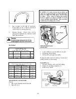
Page 46: ...washer over hole in water line Turn saddle valve handle clockwise to expose piercing lance a maximum of 3 16 4 5cm Align piercing lance over hole in water line Place both halves of saddle valve brack...

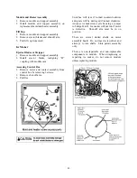
Page 47: ...pper strips on backside of drive gear As the drive gear rotates contacts will make or break a circuit tract to the copper strips to operate ice maker Test points are identified on module N Neutral sid...

Page 48: ...T H Bimetal Open Closed L H Heater On Off L M Motor On Off N V Water Valve On Off DISASSEMBLY PROCEDURES Cover 1 Pull water adjustment knob forward 2 Snap off cover WARNING To avoid electrical shock w...

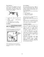
Page 49: ...tor and contact assembly from control box be removing 3 screws 2 Remove shut off arm 3 Pull free Switches will jam if turned counterclockwise and gears will be destroyed if turned clockwise Advance ic...

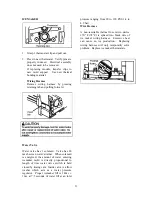
Page 50: ...ting properly If water valve does not close the following could occur no ice production small or hollow ice cubes flooding of ice container Install water filter to eliminate bad taste odor and visible...

Page 51: ...olenoid is energized the amount of water entering icemaker mold is directly proportional to length of time water valve switch is held closed by timing cam Inside valve is a flow washer which acts as a...

Reviews: