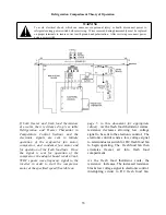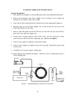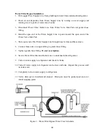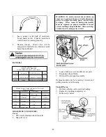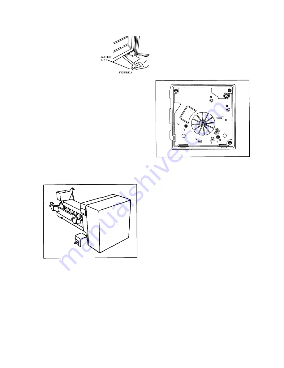
1. Pull copper line from
plumbing forward
from underneath
refrigerator (see fig.
A.) Flush air and
impurities from water
line be turning on
water supply and running two (2) quarts
of water into a bucket.
2. Connect brass fitting (located in
literature packet) to plastic line with nut
and sleeve.
3. Turn on water supply to refrigerator and
check for leaks.
4. Turn off water supply to refrigerator and
correct any leaks. Repeat this process
until no leaks exist.
5. Completely turn on water supply to
refrigerator.
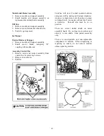
6. Verify drain pan is installed and aligned
properly. Drain pan must be pushed
past and over initial stopping point.
ICE MAKER
Operation
Thermostat closes when temperature reaches
17
°
±
3
°
F (-8.3
°
±
1.5
°
C). Current flows
through thermostat to motor. See “Ice
Maker Wiring Diagram”. Motor is linked
with drive gear. From module, there are
copper contacts that ride on copper strips on
backside of drive gear. As the drive gear
rotates, contacts will make or break a circuit
(tract) to the copper strips to operate ice
maker.
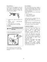
Test points are identified on module:
N = Neutral side of line
M = Motor connection
H = Heater connection
T = Thermostat connection
L = L1 side of line
V = Water valve connection
Specifications
Mold heater: 185 watts, 264 ohms
Thermostat: Close 17
±
3
°
F (-8
±
1
°
C)
(Bimetal) Opens 32
±
3
°
F (0
±
1
°
C)
Water fill: 140 cc, 7.5 sec.
Motor cycle Stamped in circuit.
Plug in connectors
One revolution of blades takes
3 minutes plug stall time on ice
Testing Procedures
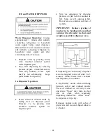
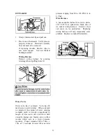
Verify ice maker has power, shut off arm is
down, and freezer is cold enough to close
bimetal thermostat.
•
Test point L and N will verify 120
volts to ice maker module.
•
Test point T and H will verify bimetal
thermostat is open or closed.
•
Verify test probes go into test points
½ inch (1.25 cm).
1. Short T and H with a shunt
(insulated 14 gauge wire with ends
stripped back 5/8 inch (1.6 cm) to
run motor. If motor runs. Replace
bimetal thermostat. If motor does
not run, replace module.
47
Summary of Contents for DFSB483D
Page 1: ...VCSB483D DFSB483D DDSB483D COVER F90597...
Page 4: ...VCSB483D with ICE and WATER 4...
Page 5: ...CABINET AIR FLOW 5...
Page 6: ...MACHINE COMPARTMENT AIR FLOW 6...
Page 7: ...REFRIGERANT FLOW 7...
Page 8: ...WATER FLOW 8...
Page 27: ...VCSB483 WIRING DIAGRAM 27 27...
Page 28: ...VCSB483D WIRING DIAGRAM DISPENSER MODEL 28...
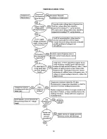
Page 38: ...CONTROL BOARD OPERATION 38...
Page 39: ...TROUBLESHOOTING 39...
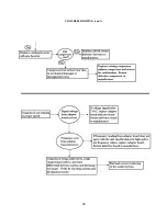
Page 40: ...TROUBLESHOOTING con t 40...
Page 45: ...45...

