Disassembly
© Viking Range Corporation
SMR-0003
21
Thermistors
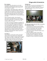
Disconnect power.
1.
Remove back panel and lower shroud.
2.
Disconnect the evaporator thermistor connector at
3.
the electronic controller.
Remove evaporator thermistor by removing the
4.
screw securing it.
Feed the thermistor wire out through the opening in
5.
the back of the unit.
Reverse the removal procedure for installation.
6.
Lights
For Wine Cellars:
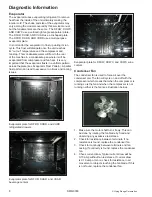
The wine cellars are equipped with two 6 watt tube lights
located on the inside top of the cabinet.
Replacing the Tube Light:
Disconnect power to the unit.
1.
Remove the bulb from the channel in which it sits.
2.
Each light is fit snugly into the channel so you might
need to use a screwdriver or knife to help loosen it.
Once the bulb is out of the channel, unplug it from
3.
the connector and set it aside.
Plug the new bulb into the connector and press
4.
the bulb snugly into the channel. You might need
to press or tap firmly to place the bulb back in the
channel.
Reconnect power to the unit and check to see if the
5.
light tube operates properly.
For Beverage Centers:
The beverage centers are equipped with a 15 watt light
bulb located behind the display housing on the inside top
of the cabinet.
Replacing the Light Bulb:
Disconnect power to the unit.
1.
Unscrew the old light bulb located behind the display
2.
housing.
Set the old light bulb aside to discard.
3.
Screw the new light bulb into place.
4.
Reconnect power to the unit and check to see if the
5.
light bulb operates properly.
For Refrigerated Drawers:
The refrigerated drawers are equipped with two LED
lights: one on the inside top of the drawer and one on
the underside of the divider.
Condenser
Removing the condenser
Disconnect power to the unit.
1.
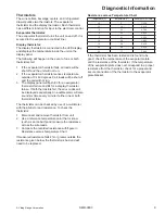
Remove back panel and lower shroud.
2.
Remove the screws that hold the baseplate to the
3.
chair frame of the unit and slide out the mechanical
baseplate.
Install sealed system access valve(s) and recover
4.
refrigerant. After recovering, be sure to cap off the
access valve(s) to prevent contamination of the
system.
Remove the condenser fan by removing the
5.
four screws on the fan mounting bracket at the
baseplate. The fan wire leads can be left connected.
Set the fan assembly to the side out of the
mechanical.
Remove the condenser fan shroud.
6.
Un-braze capillary tube from drier assembly.
7.
Un-braze high side tubing from the compressor.
8.
Remove the condenser and drier assembly.
9.
Installing the condenser
Reverse the removal procedure for installation.
•
Always install a new drier after opening the sealed
•
system.
Be sure to flush the system and evacuate to 50
•
microns before weight charging.
If contamination was found or determined, the
•
evaporator should also be replaced at this time.
Condenser Fan
Disconnect power to the unit.
1.
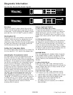
Remove access panel and rear panel.
2.
Remove the grille by removing the screws and
3.
disconnecting the wires to the rocker switch. Be sure
to mark where these wires go for reassembly.
Take out the screws that secure the top of the
4.
electrical bracket located in the front of the
mechanical area.
Remove the screws that secure the baseplate to the
5.
cabinet on the bottom of the unit.
Gently slide the mechanical out the back of the unit
6.
to gain access to the condenser fan.
Disconnect the neutral white wire lead (black ribbed
7.
wire) and hot wire lead (black smooth wire) from the
wire harness.
Remove the condenser fan.
8.
Reverse the removal procedure for installation.
9.
To avoid risk of electrical shock, personal injury, or death, disconnect electrical power source to unit, unless test
procedures require power to be connected. Discharge capacitor through a resistor before attempting to service.
Ensure all ground wires are connected before certifying unit as repaired and/or operational.

