Table of Contents
© Viking Range Corporation
SMR-0003
3
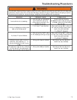
Troubleshooting Procedures ........................................
13
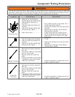
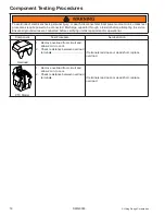
Component Testing Procedures ...................................
16
Disassembly
.................................................................
19
Mechanical Baseplate: .............................................
19
Compressor ..............................................................
20
Condenser
................................................................
21
Condenser Fan ........................................................
21
Thermistors
..............................................................
21
Lights ........................................................................
21
Wiring Diagrams and Schematics ................................
23
Wine Cellar Wiring Schematic ..................................
23
Beverage Center Wiring Schematic .........................
24
Refrigerated Drawer Wiring Schematic ....................
25
Important Information .....................................................
2
Important Notices for Service Technicians .................
2
General Information .......................................................
4
Unit Specifications ......................................................
4
Wine Cellar, Beverage Center & Refrigerated Drawers
Unit Specifications ......................................................
4
Serial Nameplate ........................................................
4
Before Servicing .........................................................
4
Basic Refrigeration Tools ...........................................
5
Installation ..................................................................
5
Electrical Requirements .............................................
5
Sealed System Basics ...............................................
5
Diagnostic Information ...................................................
6
Low Side leaks ...........................................................
6
High Side Leaks .........................................................
6
Restricted Capillary Tube ...........................................
6
Access Valves ............................................................
6
Evaporator Frost Pattern ............................................
6
Pressure and Temperature .........................................
6
Temperature-Pressure Chart for R-134a ....................
6
Re-charging ................................................................
7
Condenser
..................................................................
7
Compressor ................................................................
7
Evaporator ..................................................................
8
Thermistors
................................................................
9
Resistance versus Temperature Chart .......................
9
User Interface Panel and Tru Protect™ System ......
10
Starting the Unit
.......................................................
10
Setting the Temperature Mode .................................
10
Adjusting the Temperature Control ...........................
10
Interior Light and Switch ...........................................
10
Sabbath Mode
..........................................................
10
Warning Alarm ..........................................................
11
Resetting the Alarms ................................................
11
Show Room Mode ....................................................
11
Error Code Detection ...............................................
11
Error Code Detection Reference ..............................
11
Service Diagnostics Mode ........................................
12
Software Model Number ..........................................
12
Available Component Tests ......................................
12
Ordering Parts ..........................................................
12

