background image

Diagnostic Information

8

SMR-0003

© Viking Range Corporation

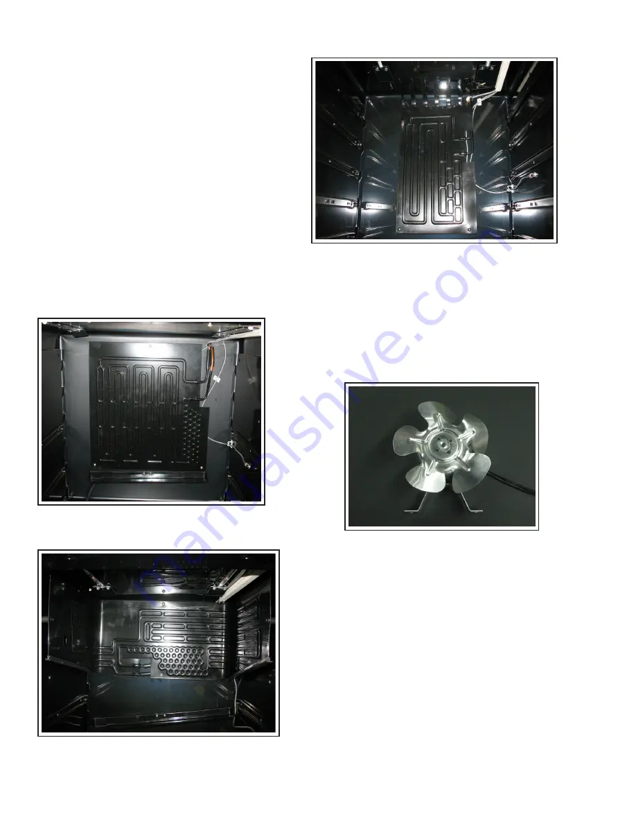
Evaporator plate for DFUW, DUWC, and VUWC wine 

coolers

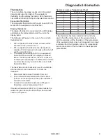
Condenser Fan

The condenser fan is used to force air over the 

condenser coil. The fan will cycle on and off with the 

compressor which means that when the compressor is 

running so is the fan and when the compressor is not 

running neither is the fan (see illustration below).

Make sure the motor shaft turns freely. This can 

1. 

be done by rotating the fan blade by hand and 

observing any excessive resistance.

Check for resistance between terminals. If no 

2. 

resistance is found, replace the condenser fan.

Check for continuity between terminals and fan 

3. 

casing. If continuity is found, replace the condenser 

fan.

Check current draw. Typical current draw will be 

4. 

0.15 amp without fan resistance. If current draw 

is 0.19 amp or more, check for resistance in air 

movement or objects touching the fan blade. If this 

is not found, replace the condenser fan.

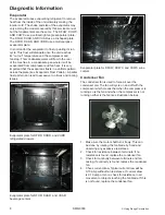
Evaporator

The evaporator uses evaporating refrigerant to remove 

heat from the inside of the unit ultimately making the 

interior cold. The shape and size of the evaporator may 

vary among the models covered by this service manual 

but the fundamentals are the same . The DFUW, DUWC, 

AND VUWC use a vertical right angle evaporator plate. 

The DFUR, DUAR, AND VUAR use a U-shaped plate. 

The DFRD, DURD, AND VURD use a multi-purpose 

evaporator plate.
It is normal for the evaporator to frost up during its run 

cycle. This frost will dissipate once the unit reaches 

its “cut out” temperature and the compressor and 

fan stop. This condensate water will flow to the rear 

of the machine in a condensate pan where it will be 

evaporated from compressor and fan heat. It is very 

important that the evaporator frosts in a uniform pattern 

across the plate (see Evaporator Frost Pattern). A partial 

frost pattern can lead to excessive run times and cooling 

issues.

Evaporator plate for DFRD, DURD, and VURD 

refrigerated drawers

Evaporator plate for DFUR, DUAR, and, VUAR 

beverage centers

Summary of Contents for DFUR144

Page 1: ...nal injury for improper service procedures done by an unqualified person Service SMR 0003 July 2008 DFRD144 DFUR143 DFUR144 DFUW144 DUAR143 DUAR144 DURD144 DUWC144 VUAR143 VUAR144 VURD144 VUWC144 2008...

Page 2: ...IT IS THE TECHNICIANS RESPONSIBILITY TO REVIEW ALL APPROPRIATE SERVICE INFORMATION BEFORE BEGINNING REPAIRS All safety information must be followed as provided in this document To avoid risk of elect...

Page 3: ...ic Refrigeration Tools 5 Installation 5 Electrical Requirements 5 Sealed System Basics 5 Diagnostic Information 6 Low Side leaks 6 High Side Leaks 6 Restricted Capillary Tube 6 Access Valves 6 Evapora...

Page 4: ...vary among the models listed in this service manual See chart below for unit specifications related to the model that you are servicing Wine Cellar Beverage Center Refrigerated Drawers Unit Specifica...

Page 5: ...h dry nitrogen gas 6 after final brazing This will flush out any air or moisture that may have entered the system before being absorbed into the ester oil Basic Refrigeration Tools The following list...

Page 6: ...be flushed thoroughly with nitrogen gas and evacuated to 50 microns before re charging High Side Leaks High side leaks consist of a break in the system at the condenser high side tubing drier or capil...

Page 7: ...the access valve on the compressor s process tube If any access valve is attached to the high side process tube remove it and then seal the tube by brazing before charging Charge the unit to specified...

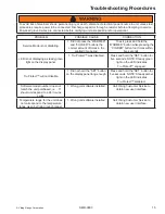
Page 8: ...ade If this is not found replace the condenser fan Evaporator The evaporator uses evaporating refrigerant to remove heat from the inside of the unit ultimately making the interior cold The shape and s...

Page 9: ...ermistor is connected to the LED display and displays the temperature inside the unit on the display panel The following will happen in the event of one or both thermistors fail If the evaporator ther...

Page 10: ...d ALARMS OFF Steady Amber PRESS ON OFF Reset SET WARMER COLDER F C LIGHT OFF PRESS AND HOLD TruProtect System POWER FAILURE Flashing Amber HIGH LOW TEMP Red ALARMS OFF Steady Amber PRESS ON OFF Reset...

Page 11: ...or more than five 1 5 minutes an audible alarm will sound three 3 times every 30 seconds and the LED light will flash green This will stop as soon as the door is closed High and Low Temperature If the...

Page 12: ...e Service Mode press and hold the WARMER button while pressing the COLDER button four times within five seconds You cannot enable Service Mode while in Set Mode All system functions will remain in the...

Page 13: ...until the LIGHT button is pressed again 2 The light bulb is burned out Replace the light bulb and then press LIGHT button Door is closed but the light is still on inside of the unit 1 Did not press t...

Page 14: ...y minute Compressor fault high low amps 1 Compressor wires disconnected Check wiring diagram on back of unit and reconnect wires 2 Faulty compressor Replace compressor 3 Faulty control Replace control...

Page 15: ...times within five seconds LED is not displaying a steady green light on the display panel 1 Tru Protect was disabled Press and hold the SET button for five seconds NOTE Steady green light on the LED...

Page 16: ...ross the following Start winding Run winding See Compressor section Run Common Start terminals to compressor housing If run winding or start winding reads high to infinite resistance open replace comp...

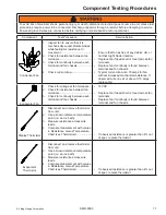
Page 17: ...if dead short is found across fan terminals Replace fan if continuity is found between terminal and fan chassis Display Thermistor Disconnect and remove thermistor 1 from unit Use a known reference te...

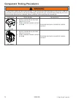
Page 18: ...arter Remove overload from circuit and 1 allow 2 min to cool Check resistance between overload 2 terminals If terminals read open or dead short replace overload To avoid risk of electrical shock perso...

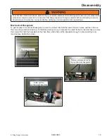
Page 19: ...te to the chair frame and slide out the baseplate enough to allow working room required see illustration below Remove Screws Slide out the mechanical baseplate Remove screws securing the mechanical ba...

Page 20: ...nd install the three sleeves where the carriage bolts will be located Mount the new compressor and install the three washers and lock nuts and tighten to 45 in lbs DO NOT REMOVE THE RUBBER PLUGS AT TH...

Page 21: ...screws that hold the baseplate to the 3 chair frame of the unit and slide out the mechanical baseplate Install sealed system access valve s and recover 4 refrigerant After recovering be sure to cap of...

Page 22: ...er for easier access to the lens 2 assembly Be careful not to disturb other wiring inside the unit Press in on the lens release tabs while 3 simultaneously prying the lens upward using a flat blade sc...

Page 23: ...OARD USER INTERFACE BOARD DOOR MAGNET REED SWITCH BLK WHT BLK YEL WHITE RED WHT BLK YEL YEL WHT RED BLU WHT YEL COMM CONTROL BOARD DETAIL TOP VIEW ORG WHITE WHITE BLK YEL BLUE TAN J5 J8 J6 J4 J4A J7 L...

Page 24: ...CORD CONTROL BOARD USER INTERFACE BOARD DOOR MAGNET REED SWITCH WHT BLK YEL WHITE RED WHT BLK WHT BLU WHT YEL COMM CONTROL BOARD DETAIL TOP VIEW ORG WHITE WHITE BLK YEL BLUE TAN J5 J8 J6 J4 J4A J7 LI...

Page 25: ...GNET REED SWITCH GND BLK BLK YEL WHITE BLK YEL GRN ORG RED BLK WHT RED COMM CONTROL BOARD DETAIL TOP VIEW ORG WHITE WHITE BLK YEL BLUE TAN J5 J8 J6 J4 J4A J7 LINE NEU CHASSIS GND GRN USER INTERFACE BO...

Reviews: