Installation
1
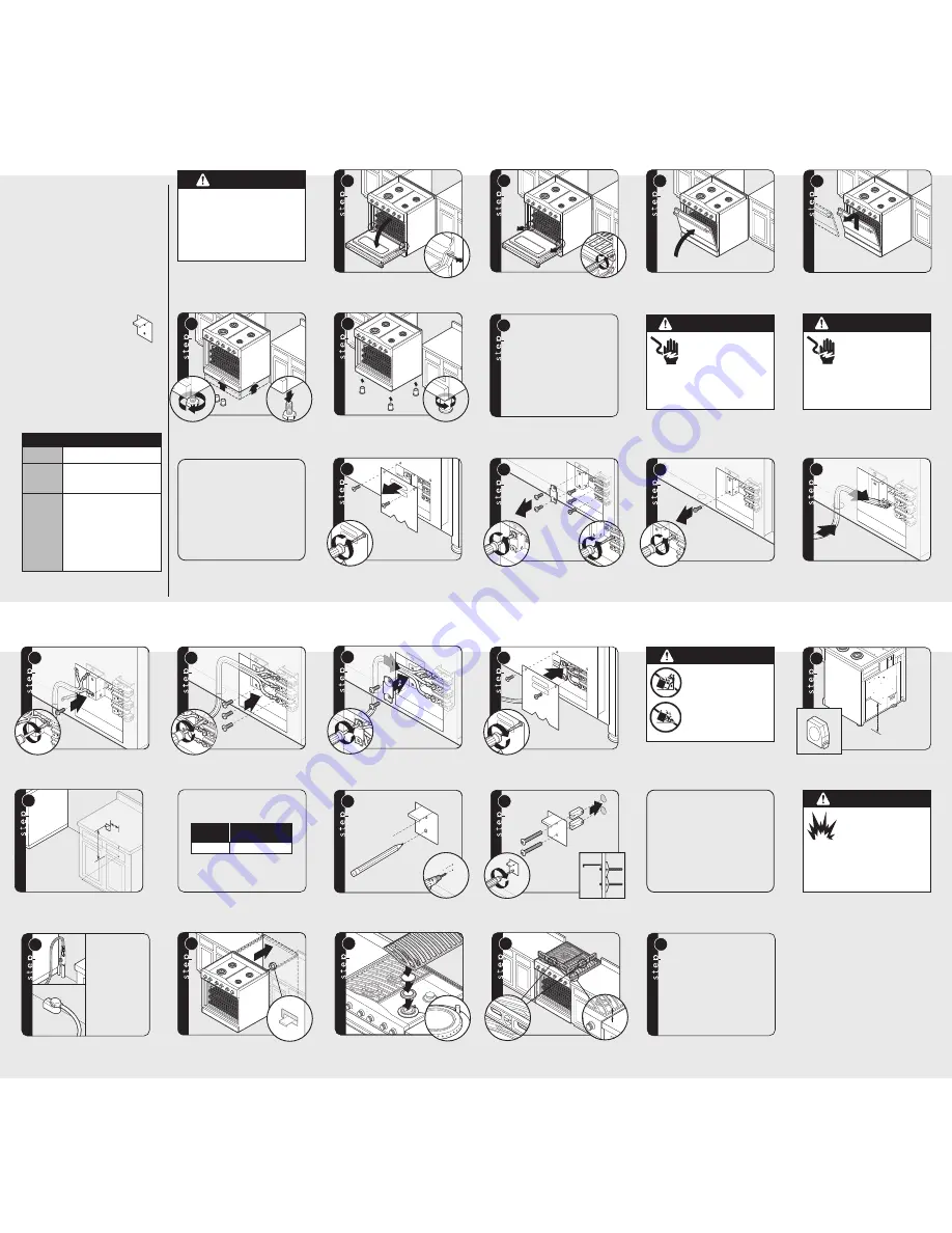
Open door completely. Place pins, supplied
with unit, in pin hole. For personal safety,
ONLY
use pins supplied with the unit.
General Information
17
Me
as
ure
me
nt
(A
)
Measur
ement (A)
+1
/2
”
+1/2”
(1.
3 c
m)
(1.3 cm)
Me
as
ure
me
nt
(A
)
+1
/2
”
(1.
3 c
m)
X
X
X
2
3
Remove hinge trim screws. Take off
hinge trim. Identify right and left hinge
for future re-installation.
Close until pins stop door.
Lift door up and out.
4
Legs are packed in styrofoam top pack.
Note:
Legs should be installed near to
where appliance is to be used, as they are
not secure for long transit.
16
Me
asu
rem
ent
(A)
Measur
ement (A)
Me
asu
rem
ent
(A)
READ AND FOLLOW ALL WARNING AND CAUTION
INFORMATION WHEN INSTALLING THIS APPLIANCE.
• All openings in the wall behind the appliance and in
the floor under the appliance must be sealed.
•
DO NOT
obstruct the flow of combustion and
ventilation air.
Moving, Handling, and Unpacking
Remove and discard all packing materials, including
cardboard and tape on the outside and inside of the
range.
Remove the cardboard pack that contains the grates,
burner heads, burner caps, leveling legs, and anti-tip
bracket off the top cooking surface.
DO NOT
discard the anti-tip metal bracket
supplied with the range. This is the anti-tip
device and must be installed with the unit.
Refer to Steps 16-19.
Some stainless steel parts may have a plastic
protective wrap which must be peeled off. The interior
should be washed thoroughly with hot, soapy water to
remove film residues and any dust or debris before
being used, then rinsed and wiped dry. Solutions
stronger than soap and water are rarely needed.
N O T I C E
DO NOT
use the handle or oven door to
lift the range. Remove door before
installation to ensure that it is not used to
lift the unit.
DO NOT
lift or carry the door
by the handle.
Removing the door must be done by your
dealer, a qualified licensed plumber, or
certified gas installer.
Dimensions
1
1
5
3
2
6
Screw legs into couplings on all four corners.
Lower range gently to keep any undue strain
from legs and internal mounting hardware.
7
Note:
For Leveling, Adjustment,
and Alignment refer to the
Installation Guide.
W A R N I N G
TIPPING HAZARD
To reduce the risk of property
damage or personal injury;
install anti-tipping device
provided in accordance with
the installation instructions in
this document. Device must be
engaged properly to prevent
product from tipping over.
Mark and drill holes where
bracket will be located.
Anti-tip location for range width.
18
Note:
It is strongly recommended that a pallet
or lift jack be used rather than tilting. Raise
unit about a foot. Unscrew temporary legs
from couplings.
Attach bracket with
mounting hardware provided.
19
Note:
Refer to
“Electrical & Gas
Requirements”
section for
proper
installation
information.
20
21
22
3/
8”
3/8”
(0.
95
cm
)
(0.95 cm)
3/
8”
(0.
95
cm
)
23
24
Note:
For Door Replacement,
reverse Steps 1-3
For Door Adjustment, refer to
the Installation Guide.
Measure from floor to
bottom of the anti-tip opening
located on the back of range. This
will be measurement (A).
Slide range into place. Be sure
anti-tip bracket slides into the anti-tip opening.
Burner heads and burner caps are packed
in the cardboard top pack with the grates.
Align burner head on burner base. Place
burner cap on burner head. Place grates
onto the burner pan.
Check that unit is level side to side and front to
back. The side trim must be 3/8” (0.95 cm)
above countertop. If unit is not level repeat
steps 5-7 of
“Leveling/Adjustments/
Alignment”
section of
Installation Guide.
D A N G E R
GAS LEAK HAZARD
To avoid risk of personal injury
or death; leak testing of the
appliance must be conducted
according to the manufacturer’s
instructions. Before placing appliance in
operation, always check for gas leaks with
soapy water solution.
• DO NOT USE AN OPEN FLAME TO
CHECK FOR GAS LEAKS.
Connect gas and electrical. Before placing
appliance in operation, always check for gas leaks.
This must be performed by your dealer, a qualified
licensed plumber, or gas service company.
Locate anti-tip bracket on rear wall with the top left
corner at measurement (A) plus 1/2” (1.3 cm) from
the floor and “X” from where the right side of
range (facing range) is to be located.
W A R N I N G
ELECTRICAL SHOCK
HAZARD
To avoid risk of electrical
shock, personal injury or
death; verify your appliance has been
properly grounded in accordance with local
codes or in absence of codes, with the
National Electrical Code (NEC),
ANSI/NFPA 70-latest edition.
W A R N I N G
ELECTRICAL SHOCK
HAZARD
To avoid risk of electrical
shock, personal injury or
death; grounding product to the frame of
the unit may or may not be permitted
through your local codes. If ground to the
frame is not permitted then a 4 conductor
power cord must be used.
Where local codes do not permit grounding
through neutral, use a 4-wire power supply cord.
The cord or conduit must be secured to the
range with the strain relief bracket.
The electrical connection is made at the
terminal block, which is located behind the
access door on the back of the range.
8
9
10
4-wire only
4-wire only
Remove access door.
Remove supply cord strain relief
bracket and three supply cord mounting
screws on the terminal block.
Remove grounding screw. Cut-off
and discard ground strap.
Feed supply cord up through hole in bottom
of range back.
11
12
4-wire only
4-wire only
Attach ground lead (green)
with ground screw that was removed.
13
1
1
14
Push supply cord toward terminal
block to relieve strain, reattach supply cord
strain relief bracket over supply cord.
15
Reattach access door.
Installation
(cont.)
Attach line #1 (black) and line #2 (red) leads
to outside terminal. Attach neutral wire (white)
to center terminal on terminal block.
Range
Width
“X”
Dimension
30”
3-5/8” (9.2 cm)
Note:
Standoff brackets can only be
removed if range is installed against a
NON-COMBUSTIBLE
wall.
Note:
For Standoff Bracket Removal
refer to the Installation Guide.
Description
30”W.
Overall width
29-7/8” (75.9 cm)
Overall height
– To top of
side trim
– Legs adjust
35-7/8” (91.1 cm) min. to
37” (94 cm) max.
1-1/8” (2.9 cm)
Overall depth
(from rear)*
– To front of
side panel
– To front of
landing ledge
– To front of
door handle
– To front of
door
25” (63.5 cm)
26-1/2” (67.3 cm)
28-1/4” (71.8 cm)
25-3/4” (65.4 cm)


