background image

11

10

1

7

2

x2

8

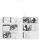
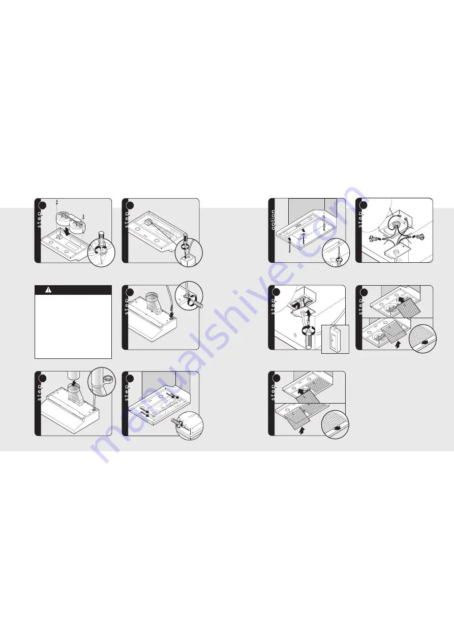
Reinstall blower. Ensure that blower
opening faces the rear of the hood.

Remove electrical box cover.

1

9

2

Insert 6” of electrical wiring through the top of vent hood

and secure using wiring restrain. Refer to local codes.

10

11

5/16”

nut driver

Slide duct over transition and tape around joint.

CAUTION:

Secure vent hood to

wall using screws provided. Use additional

mounting screws and wall anchors, if necessary.

Installation

(Top duct cont.)

W A R N I N G

To reduce the risk of fire, electric shock, or
injury to persons, observe the following:

• Use this unit only in the manner intended

by the manufacturer. If you have any

questions, contact the manufacturer.

• Before servicing or cleaning unit, switch

power off at service panel and lock service

panel to prevent power from being

switched on accidentally. When the service

disconnecting means cannot be locked,

securely fasten a prominent warning

device, such as a tag, to the service panel.

Bare or green

White

White

Green

Green

Green

Black

Black

Black

Black

12

1

1

2

3

13

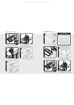
Connect black to black, white to white, and 
the green/bare wire under the green screw.

Note:

Housing wiring must be properly installed 

for wiring to be correct when wiring unit.

Replace electrical box cover. 

Make connection to breaker box.

1

2

3

14

15

11

2

3

Slide filter front over front lip. Push filter 

rear up, then slide back over rear lip.

Slide filter front over front lip. Push filter 

rear up, then slide back over rear lip.

Installation

(Top duct cont.)

5/16”

nut driver

CAUTION:

Using screws provided, make sure top

mounting screws are secured into soffit or cabinet

frame. Use additional mounting screws, if necessary. 

All manuals and user guides at all-guides.com

all-guides.com

Summary of Contents for DWH3006SS

Page 1: ...ration 111 Front Street Greenwood Mississippi 38930 USA 662 455 1200 For product information call 1 888 VIKING1 845 4641 or visit the Viking Web site at vikingrange com F20569A EN 022409J All manuals...

Page 2: ...y important safety messages in this manual and on your appliance Always read and obey all safety messages This is the safety alert symbol This symbol alerts you to hazards that can kill or hurt you an...

Page 3: ...to persons in the event of a rangetop grease fire observe the following Based on Kitchen Firesafety Tips published by NFPA Smother flames with a close fitted lid cookie sheet or metal tray then turn o...

Page 4: ...cm 2 3 16 5 6 cm 1 5 8 4 1 cm 1 5 8 4 1 cm Electrical hookup 3 1 4 x 10 Duct location A 30 W 29 7 8 75 9 cm 36 W 35 7 8 91 1 cm B 30 W 9 15 16 25 2 cm 36 W 12 15 16 32 9 cm C 30 W 14 15 16 37 9 cm 36...

Page 5: ...e of blower you are using Recommended hood locations for the most common installations are shown Adjust your measurements for various heights of ceilings soffits cabinets or ranges rangetops Check Fra...

Page 6: ...el to prevent power from being switched on accidentally When the service disconnecting means cannot be locked securely fasten a prominent warning device such as a tag to the service panel Bare or gree...

Page 7: ...l codes 10 11 5 16 nut driver Slide duct over transition and tape around joint CAUTION Secure vent hood to wall using screws provided Use additional mounting screws and wall anchors if necessary Insta...

Page 8: ...o black white to white and the green bare wire under the green screw Note Housing wiring must be properly installed for wiring to be correct when wiring unit Installation Recirculating Note Hood ships...

Page 9: ...d be referred to a qualified technician Record the following information indicated below You will need it if service is ever required The serial number and model number for your appliance are located...

Page 10: ...____________________________________________________________________________ 18 Notes __________________________________________________________________________________________________________________...

Reviews: