12
remote sprinklers as calculated. The operation of the control valve is caused by
the operation of the detection system after sensing a fire condition. The
installation position must be directly adjacent and at the bottom of the supply
riser to the area of protection and must be in a heated room that maintains a
minimum temperature of 40
°
F (4 °C).
•
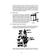
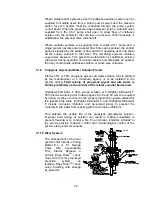
The primary Easy Riser
TM
Check Valve is a Viking Model F-1 that includes a
system main drain, inlet connection for antifreeze supply, system pressure
switch, system supervisory switch and gauges to monitor system antifreeze
pressure and control the CS-1 antifreeze pump system. This check valve must
be located downstream of the deluge valve (within 1 to 2 ft maximum). It is
recommended to install this check valve as close to floor level as convenient in
order to properly maintain the valve. The inlet side of valve is atmospheric air,
while the outlet will be the desired static antifreeze pressure to the system.
Options for the check valve include pressure relief valve (see selection below)
and automatic pressure control system for variable temperature freezers and
coolers described below.
•
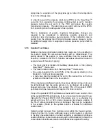
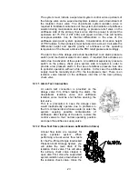
A second thermal isolation valve (Viking Model F-1 Easy Riser
TM
Swing Check
Valve) is installed as close to the freezer wall as possible but at least 5 ft above
or downstream of the primary check valve within the heated area of the riser
room to prevent thermal migration of the antifreeze from the freezer and protect
the primary check valve from freezing near the atmospheric air surface of the
clapper and seat. This valve includes a main drain and a special 3/8” I.D. copper
tube by-pass to allow proper system pressure monitoring and prevent thermal
migration to primary check valve. The main drain must be piped to the main drain
of the primary check valve and returned to the recovery tank.
•
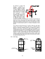
Releasing control panel shall be a listed releasing panel capable of single hazard
and two-zone operation. The control panel shall be provided with a 90-hour
backup battery supply. Zone 1 shall operate the releasing circuit and alarm. Zone
2 shall detect low pressure antifreeze and provide alarm.
•
Detection is required for this system. The detection system shall be capable of
operation prior to or equal to an ESFR Sprinkler having an RTI (Response Time
Index) of 50 or less. No linear detection shall be allowed. This limits the system
to low temp spot heat, beam smoke or air sample type smoke system or equal.
5.0
SYSTEM INSTALLATION REQUIREMENTS AND CONSIDERATIONS
5.1 Tree Configuration - ESFR Cold Storage System
A tree type piping configuration is required for this type system over the grid type
system because this type of system is easier to set up for drainage. Also, with a
center feed main supplying branch lines, the flow is directed toward the first open
sprinklers. This allows the antifreeze solution to be expelled from lines and mains
leading directly to open sprinklers and to be replaced with 100% water much
faster than in grid type systems. For tree systems utilizing this system, the mains
Summary of Contents for ESFR
Page 5: ...5 Figure 1 Straight Through Configuration...
Page 6: ...6 Figure 2 Angle Style Configuration...
Page 10: ...10...
Page 35: ...35...


