30
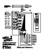
supply. The tank and pump system automatically maintains the supervisory
solution pressure in the piping above the check valves, until the detection system
is activated. When the detection system is activated, the deluge valve is operated
from the system releasing control panel. In the event of a fire condition, the
detection system operates the deluge valve and pressurizes the system with the
design discharge water pressure. The system pressure control switch is wired
through the alarm pressure switch located on the deluge valve. In a fire condition,
the CS-1 antifreeze pump unit keeps the supply solenoid valve closed that is
supplying the operated riser system. In a situation where a sprinkler opens,
breaks off, or pipe ruptures, causing a low pressure supervisory condition without
a fire condition, the low pressure supervisory switch located on the primary check
valve will provide an alarm. In this case, the antifreeze supply valve on the
alarmed riser must be manually shut off. The pump uses antifreeze in the storage
tank to maintain system pressure and make up for minor system leaks.
The system is designed to accept up to 50% propylene glycol and water premix
solution. It is recommended that Viking certified premix be used. Do not mix
different antifreeze solutions within the system.
WARNING:
Motors, electrical equipment, and controls can cause electrical arcs
that will ignite a flammable gas or vapor. Never operate or repair in or near a
flammable gas or vapor. Never store flammable liquids or gases near the unit.
SAFETY:
This equipment is designed to be safe in the use for which it was
planned, provided it is installed, started up, operated, and maintained in
accordance with the instructions in this manual. Therefore, all personnel who
install, use, or maintain the equipment must understand this manual. The unit
contains electrical components that operate at line voltage and moving parts.
Before working on the unit, isolate and lock it out from the electrical supply. All
maintenance operations must be performed by qualified persons who have
knowledge in the necessary precautions.
NOTE:
The Viking ESFR Cold Storage System shall be designed by qualified fire
protection technicians, in conjunction with requirements of the Authorities Having
Jurisdiction. These systems are designed to meet the UL Listing requirements
described in Viking technical data for ESFR K25.2 Sprinkler VK510 for use with
propylene glycol/water solution, and the standards of NFPA 13 or other
organizations, and also with the provisions of governmental codes, ordinances,
and standards where applicable.
7.2 Operating
Principle
The tank and pump system maintains antifreeze in sprinkler system piping at
desired supervisory pressure 50 PSI (344 kpa) minimum recommended
pressure. A pressure switch on the unit senses the CS-1’s discharge manifold
pressure and turns the pump on as the unit pressure drops to a preset pressure,
and then stops the pump as unit pressure rises to a higher preset pressure. A
level switch mounted in the storage tank opens when the liquid level is low.
When the level switch opens, pump operation is inhibited and a set of dry
contacts changes state for the user’s supervisory system. Terminals 21, 22, and
23 are for connection of low alarm devices. Also, the primary check valve
Summary of Contents for ESFR
Page 5: ...5 Figure 1 Straight Through Configuration...
Page 6: ...6 Figure 2 Angle Style Configuration...
Page 10: ...10...
Page 35: ...35...


