32
7.3
CS-1 Control Scheme
7.3.1 General
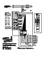
The CS-1 Tank and Pump System maintains pressure for up to six risers
with individual control to each riser. A two-way normally closed solenoid
valve is connected to each riser. The pressure maintenance switch on
each riser controls the corresponding solenoid valve. At a low riser
pressure condition, the solenoid opens, allowing flow from the CS-1 to
that riser. In the case of operation of a riser due to flow from a sprinkler,
the riser’s alarm pressure switch sends a signal to the CS-1 control panel,
and keeps the corresponding solenoid valve from opening.
A drop in pressure operates the CS-1 pump. Pump operation is controlled
by the pressure switch and level switch mounted on the CS-1. There are
two normal operating modes for the CS-1 Tank and Pump Package,
“Manual” and “Automatic”. The Manual mode is used for filling the unit’s
tank and filling systems through the CS-1, using the unit’s pump. The
Automatic mode maintains system(s) pressure(s) after filling is complete.
7.3.2 Operation
The pressure switch mounted on the CS-1 controls pump operation.
When the pressure at the CS-1 drops, the pump will turn on until the
pressure at the CS-1 rises above a set level. In “Automatic” mode, pump
operation is inhibited if the level of liquid in the unit’s storage tank drops
below the level switch height.
In “Manual” mode, the pump operates when CS-1 pressure drops, and
tank level is satisfied, and a system valve is selected, and that system
pressure is not met, and there is no alarm condition. The pump can also
fill the tank in Manual mode. For tank filling, the level switch position is not
used and the operator must start and stop the pump, using the “Hand”
position of the Hand-Off-Auto Switch on the control panel. (Note: In
order to operate in manual mode, all pressure switches must be properly
connected.)
In Automatic mode, there is a 10-minute time delay between pump
operations. After the 10-minute delay, the pump operates if the CS-1
pressure drops and tank fluid level is above the level switch height. When
the pump shuts off, the 10-minute timer starts again and the pump will not
operate until 10 minutes is complete.
7.3.3 System Solenoid Valve Operation
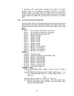
Each system (riser) pressure switch and alarm pressure switch contacts
are connected in series to one input on the PLC. The system pressure
switch closes on falling pressure. The alarm pressure switch normally
closed contacts are used and open in the alarm condition.
Summary of Contents for ESFR
Page 5: ...5 Figure 1 Straight Through Configuration...
Page 6: ...6 Figure 2 Angle Style Configuration...
Page 10: ...10...
Page 35: ...35...

