41
9.0 ALARM
SWITCH
9.1 INSTALLATION
WARNING:
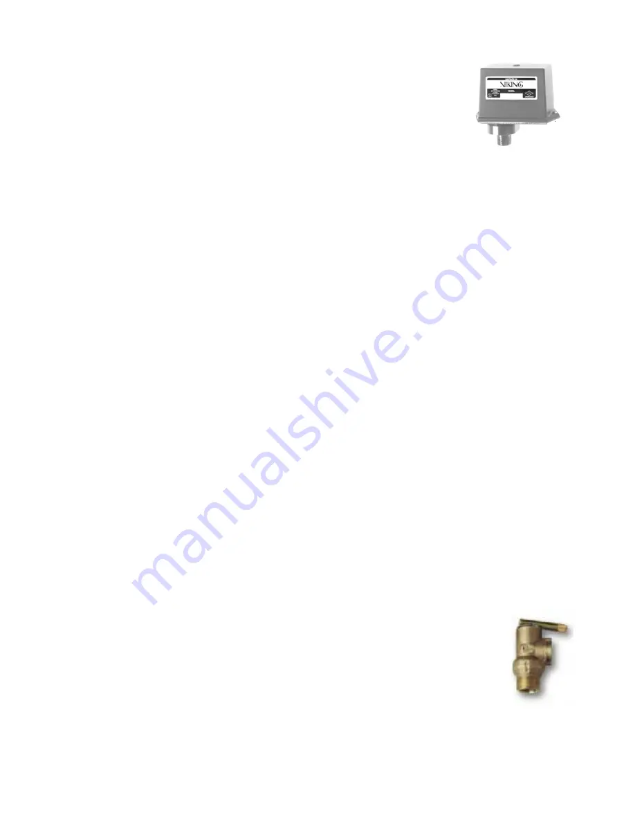
The Alarm Pressure Switches are general service
switches, not designed for use in explosive atmospheres. Refer
to the technical data page for the Explosion-Proof/Watertight Alarm Pressure
Switch intended for use in those environments.
1. Refer to the current Viking Trim Chart for the valve used to determine the
appropriate location for installing the Viking Alarm Pressure Switch on Viking
Trim. Viking Trim Sets provide:
a. An alarm connection, equipped with an alarm test valve, and an alarm shut-
off valve for switches used for local alarms and,
b. A non-interruptible alarm connection, equipped with an alarm test valve, for
switches used to signal electric alarm panels and remote alarms.
CAUTION:
Closing any shut-off valve in the alarm piping leading to the Alarm
Pressure Switch will render the switch inoperative.
2. When installing the general service Alarm Pressure Switch, apply Teflon
®
tape
sealant to the male threads only. Install the Pressure Switch in a ½" (15 mm)
pipe fitting. Use a wrench applied to the wrench flats to tighten the unit. Do not
over-tighten.
a. Mount the Alarm Pressure Switch in the upright position (threaded
connection down).
3. To wire the unit proceed as follows:
a. De-energize electrical circuits involved.
b. Use the special wrench, supplied with the switch, to loosen and remove the
tamper-resistant screws. Remove cover. Use care not to lose the rubber O-
ring screw retainers.
c. Connect conduit to the conduit opening provided. See “Technical Data” for
size of opening.
d. Connect electrical circuitry for the alarm and any auxiliary equipment being
controlled by the switch (Refer to Figures B, C, and D).
Note: Wire all devices to national and local codes and requirements of the
Authority Having Jurisdiction.
4. Replace cover and tighten the tamper-resistant screws.
5. Energize the circuits.
6. Test for proper operation of the device.
7. The switch shall be wired as a normally closed circuit.
10.0 PRESSURE
RELIEF
VALVE
The pressure relief valve relieves excess system pressure caused by surges
or temperature changes. The pressure rating of the relief valve indicates an
operating range of pressure for both opening and closing of the valve.
Standard relief valves are required to OPEN in a range of pressure between
90% and 105% of their rating. The valves are required to CLOSE at a
pressure above 80% of that rating.
Summary of Contents for ESFR
Page 5: ...5 Figure 1 Straight Through Configuration...
Page 6: ...6 Figure 2 Angle Style Configuration...
Page 10: ...10...
Page 35: ...35...


