5
Installation and Mounting
VIKING
©
1
2
3
4
5
6
7
8
9
0
#
*
9
0
#
*
8
7
6
5
4
3
2
1
Optional VE-5x10
Surface Mount Box
10.0"
9.5"
4.50"
2.596"
5.00"
8.65"
0.425"
0.952"
Front View
9.12"
2.5"
4.5"
Zinc-Plated Steel
Rough-In Box
(included)
Side View
(8) #6-32 x 1/2" Stainless
Steel, 5/64" T-10 Torx
Security Screws (included)
14 Gauge Marine Grade 316
Stainless Steel Faceplate
10.14"
3.69"
5.22"
- OR -
(not included)
see DOD# 424
Earth
Ground
Earth Ground the
Green/Yellow wire
using the
provided wire nut
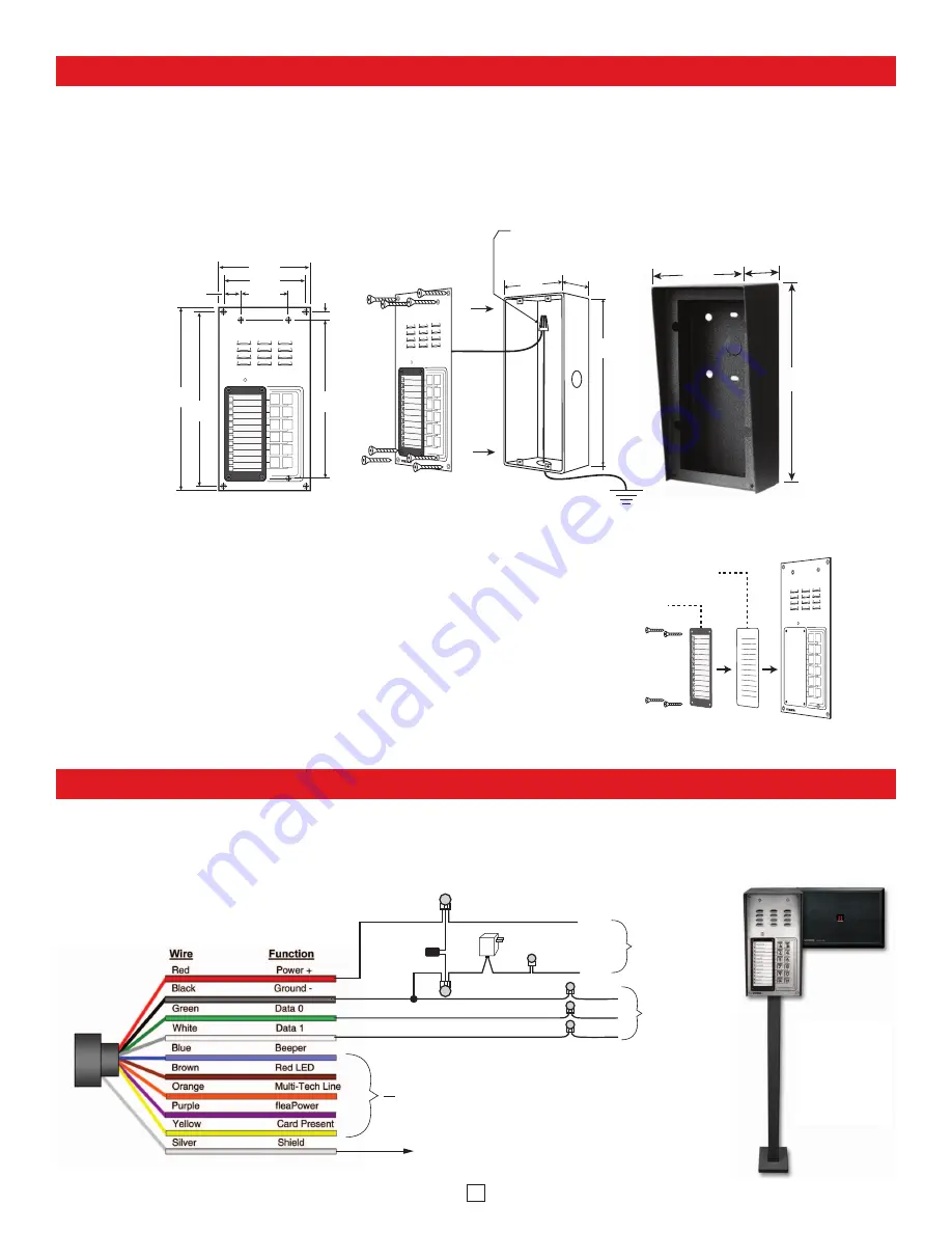
A. Mounting
The
K-1200-IP
is designed to be installed in a sheltered location, and is not meant to be used outdoors. For outdoor applications use
the
K-1200-IP-EWP
. The
K-1200-IP
can either be installed as a flush mount unit using the included rough in box, or as a surface
mount unit using an optional
VE-5x10
. The rough in box uses the inner set of four holes on the face plate while the
VE-5x10
uses
the outside set of holes. A set of dummy screws and nuts are provided to fill the unused mounting holes.
NOTE:
Write down the
MAC Address (found on the RJ-45 jack) as this may be needed to identify the unit after installation.
B. Changing the Directory
To install a directory, remove the four screws that mount the directory
lens to the front of the
K-1200-IP
using the included Allen wrench. Insert
a paper directory behind the lens and secure the two back onto the front
panel being careful to align the names with the front panel graphics.
Note:
To print directory forms for the
K-1200-IP
, go to
www.vikingelectronics.com and enter “930” in the DOD field at the top of
the page for a direct link to the PDF.
Paper Directory
Directory
Lens
Adding a Viking Model PRX-3 Medium Range Proximity Card Reader
Black
Green
White
Black
Green
White
(-) (+)
to Wiegand
input on
K-1200-IP
Connect to “-/Ground” on
Entry System / Controller and Earth GND
Keep unused leads from shorting
Connect power supply wires to
PRX-3
power
supply wires and negative lead of the controller
*
Included with PRX-3
* 12V DC
Adapter
* 2200
μ
F
Bi Polar
Capacitor
(not polarity
sensitive)
* 3 Position Butt Connectors
2 Position Butt
Connectors
(included)
to Relay 2
output contacts
on K-1200-IP
COM.
N.O.
White
Violet
When mounting a
PRX-3
in close proximity of the
K-1200-IP
(ie: using a
PRX-3-MK-GNP
mounting kit), you must set “Relay 2 mode”
to “Alarm” in Programming and wire as shown below. When using the
PRX-3
with any Viking Entry System/Controller, the provided
12V DC 500mA power adapter and 2200µF bi polar capacitor should be used. For more information on
PRX-3
, see DOD 228.
K-1200-IP-EWP
shown with
VE-5x10
,
VE-GNP
pedestal,
PRX-3-MK-VEGNP
mounting kit and
PRX-3
Card Reader,
each sold separately


